 Inventions & Experiments
of Nikola Tesla
Inventions & Experiments
of Nikola Tesla
Under construction
Generating room
- 1 Westinhouse auto compound nº 1497, size 16 by 27 by 16.
- 1 Direct connecting Westinhouse alternating current generator 200 Kw; serial nº 155407, with complete lubricator, gauge, Rheostadt, switchboard and switches.
- 1 Westinhouse engine nº 4750, size 8 (1/2) by 8, with direct connected double current generator, 25 Kw; serial nº 168362, complete with lubricator, gauge, Rheostadt, switchboard and switches.
- 1 15 H.P. Westinhouse motor, nº 162315.
- 4 Westinhouse transformers, 15 Kw. Type O.D.
- 1 Tank manufactured by Stoutenborough.
- 1 Truck.
- 1 Fairbank's scale.
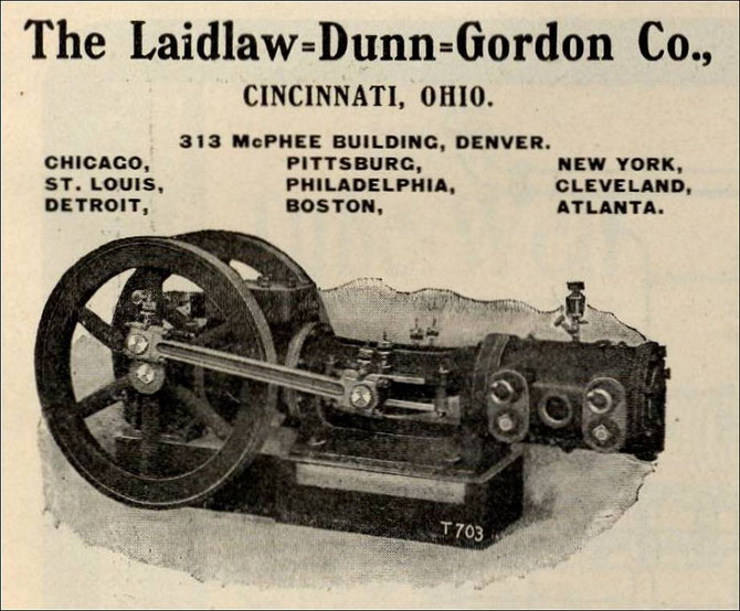
- 1 Laidlaw Dunn-Gordon pump, nº 16473.

A photograph taken in the Wardenclyffe plant generator room showing a 200 kilowatt, 3-phase direct-connecting Westinghouse alternating current generator. It was driven by a Westinghouse auto compound engine No.1497, 16 x 27 x 16 feet.
http://www.teslaradio.com/pages/wardenclyffe.htm
The energy of Tesla's steam driven Westinghouse 200 kW alternator was to be channeled instead into an underground structure consisting of iron pipes drivenm from a point 120 feet beneath the tower's base. This was to be accomplished by combining an extremely low frequency signal (ELF) along with the higher frequency current coursing between the earth and the transmitter's elevated terminal [through the master oscillator and helical resonator]. The low frequency current in the presence of an enveloping corona-induced plasma of free charge carriers would have "pumped" the earth's charge.

Courtesy of Tesla Collection. - http://teslacollection.com/
"This motor was equiped with special devices for rectifying the alternating currents and sending them into the condersers. On this apparatus alone I spent thousands of dollars. The 100 H.P. motor was specially constructed for me by the Westinhouse Company, but the other parts were all made by myself and that took a considerable portion of space there and it was a wonderful apparatus".
This machine was the main generator of 100H.P. powered by steam pressure which had to be connected under the tower to provide the power for the wireless transmission through the atmosphere.
Tesla had ordered a couple of 100 horsepower steam engines and they were installed in the power plant in November of 1901. A 300-kilowatt Westinghouse Alternator (above) was installed later.

Westinhouse auto compound
http://vintagemachinery.org/mfgindex/imagedetail.aspx?id=6203
http://vintagemachinery.org/mfgindex/imagedetail.aspx?id=3295
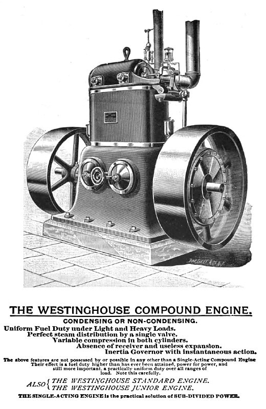
The practical success attained by the Westinghouse Automatic Engine has put beyond question the merit of the single-acting and self-lubricating principles. The development of this type of engine has been of sound and persistent growth through all stages of faults and perfections, and against unmeasured prejudice and opposition, always met when a new principle is brought forward. To describe the Westinghouse Engines in their sequence, we should begin with the "Standard" Engine; as the Compound type, of which a good engraving is shown on the opposite page, was the last style perfected.
In the creation of a totally new type of engine, many new mechanical problems were presented for solution, on which precedent in engine building gave little or no light. The engineers who designed the single-acting engine believed that ample provision had been made in every detail for the new conditions presented. The benefit of all doubt was in favor of safety. But, as in all similar cases, the old truth was ra-proven that only long continued experience in the hands of the user could develop weaknesses; and while a brief recital of the difficulties first encountered would be interesting to engineers, let it suffice to say that every weakness and imperfection has been eliminated, and the Westinghouse engines—Compound, Standard, and Junior—of to-day are as perfect as the manufacturers can produce them.
The advantages of compounding are thoroughly understood by engineers, and it is not necessary to say anything as to the economy of compound engines in general, since practical engineers are fully prepared to accept compounding as the one and only road to the highest fuel economy. Compounding is almost universal among European manufacturers, extending down to engines of the smallest size, and has been forced upon them by the close margin of manufacturing profit there obtaining.
http://vintagemachinery.org/mfgindex/imagedetail.aspx?id=3764
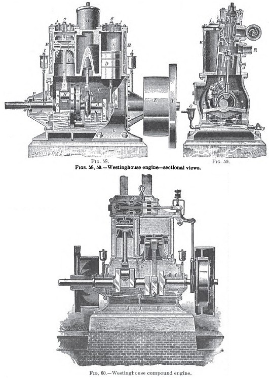
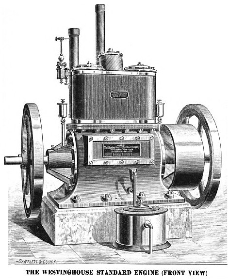
The Westinghouse Engine.—The Westinghouse engine is the leading engine of a new type which has recently come into extensive use, the principal characteristics of which are (1) two or more vertical single-acting cylinders, and (2) automatic lubrication by moans of a closed chamber surrounding the crank-shaft, containing oil or oil and water. This type of engines was originally built with two cylinders of the same size, with cranks at 180°. Large sizes are built as a compound engine, with one cylinder larger than the other. Engines on the same general principle, but with three cylinders and triple expansion, with three cranks at 120°, have been brought out by other makers. Among the advantages claimed for this type of engine are, that, on account of its being single-acting, the pressure of the piston and of the connecting-rods on the wrist and crank pins is al ways in one direction, viz., downward, and consequently, no matter how much the bearings are worn, there is no lost motion in them. On this account, the engine, if properly designed, may be run at a very high speed, and is therefore economical of room and weight, and saves the gearing for transmission of power to the line-shafting machine or dynamo, necessary with slow-speed engines. Fig. 57 shows a front view, and Figs. 58 and 59 sectional views, of the Westinghouse "standard" or non-compound engine as built in sizes from 15 to 250 horse-power. The following is a description of the details: The cylinders A A are cast in one piece with the valve-chamber B. and are bolted to the top of the bed or crank-case C. The cylinder-heads a a cover the upper ends of the cylinders only, the lower ends being uncovered and opening directly into the chamber of the crankcase. The pistons D D are of the "trunk" form, double-walled at the top to prevent condensation, open at the bottom, and carrying the hardened steel wrist-pins b b. They are each packed with three rings. The connecting-rods FF are made of forged steel. The cranks G O, the crank-pins, and crank-shaft H H are all of steel, and may be removed by taking off the crank-case head e. The crank-shaft bearings are in the form of removable shells d d, lined with Babbitt-metal. From 60 horse-power up these bearings are split for the sake of i venient removal without taking out the shaft. They are slipped into the crank-case I from the inside, and adjusted by a distance-ring /. which is of an arbitrary thickness dependent on the shrinkage of the casting of the crank-case. A chamber is formed in the outer end of the crank-case head, in which, and revolving with the shaft, is the ring-wiper u; which takes up the oil as it works past the bearings, and returns it through the hollow rib e into the crank-case C. Oil is fed to the engine from the sight-feed cups / / on the main bearings; this renders all other lubrication unnecessary, and keeps the engine clean. A siphon overflow, with a funnel head 0, prevents any accumulation of water from rising above the level of the bottom of the shaft, and thus prevents the escape of oil. This overflow may be piped off at the hole in the funnel-head to an oil-separator, shown in Fig. 59, from which it can be skimmed and restored to the crank-case. An adjustable center-bearing A' bridges the crank-case, and receives the thrust of the pistons. The bonnet A is removed, to give access to the cranks. The valve V is a piston-valve, packed with two rings in each head. The valve-seat is a removable bushing, in which the ports are cut to an exact register, and which is then forced into its shoulders. Each valve is provided with a Fig. 60.—Westinghouse compound engine. back - pressure piston, which prevents the balance of the governor from being disturbed when the engine exhausts against back-pressure. The valve-guide J serves also in lieu of a stuffing-box against the exhaust steam contained in the passage above it. The valve-guide as well as the valve and both pistons are packed with simple sprung rings of cast iron. The valve-stem m is keyed fast to the guide, and grips the valve without binding between the nut at the upper end and the collar at the lower end, as shown. The band-wheel is a combination-pulley Z and fly-wheel Y, cast together, so that the pulley overhangs the main bearing, throwing the line of belt-strain well toward the center of the bearing, and taking the spring off from the shaft. The automatic governor is located on the shaft, between the cranks, and actuates the valve direct without rock-shafts or other mechanism.
The Westinghouse Compound Engine is similar in general characteristics to the non-compound engine above described. It is shown in section in Pig. 60. One cylinder is enlarged to practically three times the area of the other. The valve-chest is across the top of the cylinders, and is in one piece, the various steam-passages being chambered in it. The valve-seat is in the form of a bush, in which the ports are cut to an exact register. This bushing is reamed out and forced steam-tight into its bored seat.
The valve-chest also contains a small by-pass valve controlling a cored passage, by which live steam can be admitted to the low-pressure cylinder, to turn the engine over its center when starting. The steam and exhaust connections, are on the side of the valve-chest toward the back of the engine. The valve is actuated by a single eccentric controlled by a shaft-governor, shown in Fig. 61. It is enclosed in a case which is filled with oil when the engine is first set up. and requires no further attention for an indefinite period. The eccentric alone is out-side of the governor-case, being carried on a shaft running through a sleeve, and bearing against stops when at full throw.
Laidlaw Dunn-Gordon pump
More info: "Compressed air plant for mines; the production, transmission and use of compressed air, with special reference to mine service (1908)" - Pg 301.
http://quarriesandbeyond.org/states/mo/mo-quarry_photos_21_da.html
St. Louis, Missouri - the Laidlaw-Dunn-Gordon Co. (Advertisement ) (from Mines and Minerals, A Mining and metallurgical Journal, June, 1902, Vol. XXII, No. 11, pp. 71):
The Laidlaw-Dunn-Gordon Co., Cincinnati, Ohio
313 McPhee Building Denver
Air Compressors - All Types - All Sizes
Chicago, St. Louis, Detroit, Pittsburg, Philadelphia, Boston, New York, Cleveland, Atlanta.
Other links to check:
-
http://quarriesandbeyond.org/states/mo/mo-quarry_photos_21_da.html
-
http://www.coppercountryexplorer.com/2009/10/mine-machines-air-compressors/
-
http://vintagemachinery.org/mfgindex/imagedetail.aspx?id=3295
-
http://vintagemachinery.org/mfgindex/imagedetail.aspx?id=3764
-
http://vintagemachinery.org/mfgindex/imagedetail.aspx?id=6203
-
http://www.nycsubway.org/wiki/The_Interborough_Power_Plant
-
http://hawkins.pair.com/wlw500kpics.shtml
-
http://www.google.co.in/patents/US696736
-
http://www.vias.org/matsch_capmag/matsch_caps_magnetics_chap6_12_06.html
-
http://www.coppercountryexplorer.com/2009/10/mine-machines-air-compressors/
-
http://www.vias.org/matsch_capmag/matsch_caps_magnetics_chap6_03.html
- http://commons.wikimedia.org/wiki/File:Construction_of_a_Westinghouse_Type_C_motor_%
28Rankin_Kennedy,_Electrical_Installations,_Vol_II,_1909%29.jpg#mediaviewer/
File:Title_page_%28Rankin_Kennedy,_Electrical_Installations,_Vol_V,_1903%29.jpg
- http://en.wikipedia.org/wiki/File:500kW_Westinghouse_rotary_converter_
%28Rankin_Kennedy,_Electrical_Installations,_Vol_II,_1909%29.jpg
- http://commons.wikimedia.org/wiki/Category:Steam_generating_sets
Write a comment