 Inventions & Experiments
of Nikola Tesla
Inventions & Experiments
of Nikola Tesla
Nikola Tesla on his work with alternating currents and Their Application to Wireless Telegraphy, Telephony and Transmission of Power: An Extended Interview
Leland I. Anderson, Editor
http://www.tfcbooks.com/tesla/nt_on_ac.htm
http://www.pbs.org/tesla/res/res_art07.html
http://books.google.cat/books?id=KRg9HWakBmQC&pg=PA45&lpg=PA45&dq=isochronous+currents&source=bl&ots=0TiG-vg_Iv&sig=s2LBnddO7LBjqaoBEAjWcJPJr9M&hl=es&sa=X&ei=5xBcVNX4MYT9PPaXgZAD&ved=0CCsQ6AEwAg#v=onepage&q=isochronous%20currents&f=false
Organization of Interview
Section
I. High Frequency Alternators
II. Experiments with Wireless Telegraphy and Telephony
III. Mechanical and Electrical Oscillators
IV. Apparatus for Transformation by Condenser Discharges; Damped Waves
V. Apparatus for Transformation by Condenser Discharges; Continuous Waves
VI. Colorado Experiments
VII. Theory and Technique of Energy Transmission
VIII. Long Island Plant
IX. Arrangements for Receiving
X. Rediscussion/Clarification of Selected Remarks
Appendix
I. Fig. 1. Photograph of Tesla with alternator in offices of The Westinghouse Electric & Manufacturing Co., May 10, 1938.
Fig. 2. Photograph of 1915 shipboard transmitter employing the Tesla spiral form of antenna transformer coil.
Index
Figures
1 Diagrammatic illustration of first high frequency alternator with 384 poles.
2 Photographic view of alternator [shown in Fig. 1].
3 Light and motive devices operated from this alternator in novel manner.
4 Vacuum tubes lighted in alternating electrostatic field.
5 Illustrating various ways of using a high frequency alternator.
6 Diagram of the second machine built with no wire on the rotating part.
7 Photograph of machine covered by U.S. Patent No. 447,921.
8 Diagrammatic drawing of the third and larger machine with 480 poles.
9 Photographic view of alternator covered by U.S. Patent No. 447,921.
10 Small alternator of very high frequency built for purposes of investigation (receivers).
11 Small high-frequency alternator of different construction, for the same purposes.
12 Diagrammatic illustration of machine with rotating magnetic field excitation.
13 Instrument to receive radio waves of 1896-1899 structure.
14 Electrical condenser described in U.S. Patent No. 464,667.
15 Electrical condenser described in U.S. Patent No. 567,818.
16 Improved form of electrolyte condenser as used in N.Y.C. laboratories.
17 Form of condenser with air under great pressure as dielectric.
18 Apparatus for manufacture of condensers and coils to exclude air.
19 Simple mechanical oscillator used in first experiments.
20 Mechanical oscillator with air spring combined with electric generator.
21 Another mechanical oscillator with controlling electromagnetic system.
22 Another type of small mechanical electromagnetically controlled oscillator.
23 Large electro-mechanical oscillator for generating isochronous oscillations.
24 Diagram of electro-mechanical oscillator for generating isochronous oscillations.
25 Double compound electro-mechanical isochronous oscillator.
26 Diagram of double compound electro-mechanical isochronous oscillator.
27 Large mechanical and electrical isochronous oscillator with four vibrating parts.
28 Diagram showing length of section of large mechanical and electrical oscillator.
29 Small high frequency mechanical and electrical oscillator used in many investigations.
30 Diagram of small high frequency electro-mechanical and electrical oscillator.
31 Method of transformation of electrical energy by oscillatory condenser discharges.
33 Discharger working in hydrogen rich atmosphere, still further weakened by heat.
34 Oscillatory apparatus with interrupter in oil.
35 Apparatus with mechanical break as installed on a large scale in the N.Y.C. labs.
36 Isochronous mechanical break used in 35 So. Fifth Avenue laboratory.
37 Mechanical break with two oppositely rotating discs.
38 Use of multi-phase generator with mechanical break.
39 Apparatus furnishing direct currents of high tension.
40 Apparatus and method of conversion by condenser discharges (both AD and DC).
41 Illustrating one of the early experiments with a tuned transformer.
42 Another illustration of an early experiment with a tuned transformer.
43 Apparatus illustrating the first step in the evolution of the magnifying transmitter.
44 One of many forms of mercury circuit controllers described in various U.S. Patents.
45 Hermetically sealed mercury circuit controller with compact oscillatory transformer.
46 Diagrammatic illustrations of hermetically enclosed mercury break.
47 Large mercury circuit controller of high frequency (communications experiments).
48 Interior arrangement of large mercury circuit controller of very high frequency.
49 Special type of high frequency transformer.
50 Illustrating forms of vacuum tubes.
51 Resonant wireless transmitting circuit.
52 Experiments illustrating transmission and transformation of energy through one wire.
53 Some of the most striking experiments with vacuum tubes and lamps.
54 The lighting of incandescent lamps by energy transmitted through one wire.
55 Experiment with the same apparatus in which a lamp is lighted at the end of a coil.
56 Another experiment with same apparatus in which the coil is not directly connected.
57 Oscillating apparatus on large scale with which the preceding experiments were made.
58 Experiment with coils tuned to harmonics.
59 Transmission of energy with tuned system by induction.
60 Application of the one-wire principle to the transmission of messages.
61 Illustrating an experiment with high frequency alternator and tuned circuit.
62 Wireless transmission demonstrated, mechanically elucidated.
63 Striking experiment in the transmission of energy by electromagnetic waves.
64 An important experiment in the transmission of energy performed in 1899.
65 Perfected system of wireless transmission with four tuned circuits.
66 Diagrams illustrating system of four-tuned circuits for wireless transmission.
67 Differences between Tesla apparatus and typical Hertz wave arrangements.
68 Powerful discharge from transmitter built following principles set forth. . . .
69 Experiment bearing upon design principles embodied in Tesla transmitter.
70 Experiment conveying idea of great quantity of electricity set in movement.
71 Wireless station at where experiments were performed.
72 Diagram showing general arrangement of transmitting and receiving circuits.
73 Experimental station at Colorado in a later phase of development.
74 Experimental station at Colorado showing investigative structure.
75 Discharge of a powerful transmitter under a pressure of 12 million volts.
76 Another discharge remarkable for symmetry at Colorado plant.
77 Diagram illustrating use of sectional circuits.
78 Experimental demonstration in the Houston Street laboratory.
79 Diagram explanatory of transmission of electrical energy.
80 Diagram illustrating one of many wireless fallacies, from a Marconi patent.
81 Diagram illustrating mode of propagation of current from the transmitter.
82 Diagram illustrating law governing passage of current from the transmitter.
83 Improved transmitter described in U.S. Patent No. 1,119,732.
84 Transmitter at Wardenclyffe, erected for purposes of —world telegraphy.—
85 Exterior view of the Long Island plant.
86 A view of some of the apparatus in the electrical part of the plant.
87 A view from a different direction.
88 Another interior view.
89 Another view showing some of the apparatus which has been described.
90 The first practical telautomaton, on principles in U.S. Patent No. 613,809.
91 Special clock, for purpose of measurements, especially useful in receiving.
92 Illustrating some of the attachments and mode of using same.
93 Devices for receiving as practiced in 1898-1900.
94 Other ways of receiving practiced in 1898-1900.
95 Illustrating bulbs made prior to 1900, many used in receiving apparatus.
96 Illustrating bulbs made prior to 1900, many used in receiving apparatus.
97 Illustrating bulbs made prior to 1900, many used in receiving apparatus.
98 Illustrating bulbs made prior to 1900, many used in receiving apparatus.
99 Illustrating bulbs made prior to 1900, many used in receiving apparatus.
100 Illustrating bulbs made prior to 1900, many used in receiving apparatus.
101 Static preventer.
Appendix Figures
A1-1 A high-frequency alternator found in Westinghouse Electric & Manufacturing Company storage identified as belonging to Tesla. —Westinghouse
A1-2 Shipboard quenched-spark transmitter, produced by the Lowenstein Radio Company and licensed under Nikola Tesla Company patents. —George Scherff
A2-1 Construction detail of Wardenclyffe plant tower. —Lillian McChesney
A2-2 Workshop on north side of Wardenclyffe plant building. —William Kolb
A2-3 Generating room of Wardenclyffe plant building. —Bruce Kelley
Preface
The surfacing of the transcript for this pre-hearing interview with Nikola Tesla by his legal counsel in 1916 resulted from an intensive search in archives of legal firms, some now defunct and others later acquired by contemporary interests. The interview was precipitated by numerous pending court cases as the fledgling radio industry entered a period of fierce competition. Tesla's counsel believed the interview necessary not only in order to prepare for the pressing of his own claims against the Marconi Company, but also to protect his own patent interests when called to give expert-witness testimony in the upcoming litigation foray pitting as adversaries a plethora of new communication companies and their captive radio pioneers.
A case prompting this interview, one of dozens to reach judicial review, was "Marconi Wireless Telegraph Company of America v. Atlantic Communication Company, et al." Atlantic owned and operated the large radio station at Sayville, Long Island. The proceedings opened in 1915 with the calling of expert witnesses including Ferdinand Braun and Nikola Tesla. The specter of war had cast its shadow over Europe, and Count George von Arco, who had also been called, was detained because of services to the German Army in the use of asphyxiating gases and other deadly inventions perfected by him.
The text of this interview was, of course, never intended for publication. Counsel, concerned primarily with the protection of Tesla's patent interests, ask questions almost exclusively relating to the priority of his patents and their application. Tesla candidly discusses his contenders while presenting a thorough history of his work with alternating currents as applied to wireless transmission. In this document, he describes experimental methods, techniques, and apparatus used in his laboratories at New York City, Colorado Springs, and Long Island.
Most of the photographs accompanying this interview are in good condition, but those of schematic and mechanical drawings have suffered some decay with time. These may be the only form of the drawings extant and are reproduced with as much fidelity as possible. For better clarity, five illustrations are reprinted from the February and May, 1913 issues of the Electrical Experimenter magazine, Copyright Gernsback Publications, where they subsequently appeared. These are Figures 66, 67, 79, 81 and 82.
Although the interview spanned several days, it is presented in this work as though it was given at one time; all references to interruptions and resumptions have been removed. The text is printed in standard typewriter pica type, unjustified, in the style of hearing proceedings of that period. No alterations have been made in Tesla's remarks except for 'clean-up' additions, typically references to photographs and diagrams, and fill-in words necessitated by occasional rambling and incomplete sentence structure. These additions are provided in brackets [ ]. Helpful notes ate also cued to the text in brackets.
L.I.A., 1992
Introduction
What I am going to show you, step by step, is how I proceeded until I finally realized my dream.
Nikola Tesla
You are holding in your hands one of the most remarkable documents in the history of electrical science. Seldom, in technical research, has such a treasure of descriptive commentary and historical documentation been discovered. This book is a veritable Rosetta stone for deciphering and tracing the technical thoughts of one of the world's most distinguished engineering scientists since Archimedes. It describes electrical experiments which took place nearly 100 years ago—but have yet to be replicated.
So astonishing are its contents that it takes one's breath away!
Here, in Tesla's own words, are interpretations (couched in the language of 19th century physics) for electrical phenomena which even today lack satisfactory explanations in the language of modern technical analysis. Oh, it won't tell you how to wire up "the magnifying transmitter" (that arcane instrument for global wireless power transmission),* but it will tell you what instruments Tesla was employing, what his thoughts were, how he conceptualized things, how he proceeded, where he performed his historic experiments, when key results were obtained, and how he reached his conclusions.
* It may just be that there is enough information present to solve the puzzle of the magnifying transmitter. The reader will have to dig for himself.
Tesla, himself, was awe-struck with the results of his scientific endeavor. He expressed astonishment then at what he later asserts is experimentally demonstrable. Listen to the words he uses in this interview to describe the electrical phenomena to his attorney: "magnificent," "it was a marvelous sight," "a wonderful thing," "practically the lamp of Aladdin," "a tremendous display," "glorious," "so marvelous that one would be almost afraid to talk about them. . . ." An Edmund Spencer or a John Milton could be no more eloquent. One of Shakespeare's characters once said, "Bid me discourse, and I will enchant thine ear." Tesla does no less, even in a legal briefing. He weaves the gossamer web of enchantment—which yet thrills our technical imagination and lures us in, nearly 80 years after a stenographer recorded these spoken words!
Who was Nikola Tesla?
In 1896, at the Franklin Institute in Philadelphia, Lord Kelvin said, "Tesla has contributed more to electrical science than any man up to his time." After showering words of praise upon the inventor before a meeting of the Royal Society in London in 1892, Lord Rayleigh declared that Tesla possessed a great gift for electrical discovery. Fortunately, the text of Tesla's speech has been preserved and republished.1,2,3 He was one of the earliest scientists to understand the distinction between lumped and distributed resonance and the first to patent voltage magnification by standing waves.
The unit of magnetic induction is named in honor of Tesla. It is commonly understood by power engineers that he was the inventor of the induction motor utilizing the rotating magnetic field and the AC polyphase power distribution system currently used throughout the civilized world.* However, most electrical engineers are unaware that, as late as 1943, he (not Marconi**) was recognized by the U.S. Supreme Court as having priority in the invention of "radio." Even fewer computer scientists are aware that, when certain computer manufacturers attempted to patent digital logic gates after World War II, the U.S. Patent Office asserted Tesla's turn-of-the-century priority in the electrical implementation of logic gates for secure communications, control systems, and robotics. As a result, a monopoly on digital logic gates in general was unable to be secured in the 1950s.
- Charles E. Scott, past president of the AIEE has said, "The evolution of electric power from the discovery of Faraday in 1831 to the initial great installation of the Tesla polyphase system in 1896 [at Niagara Falls] is undoubtedly the most tremendous event in all engineering history. [Electrical Engineering, August, 1943 (Vol. 62, No. 8), pp. 351-355.]
- Although it took the courts several decades to figure this out, the facts were well understood by impartial technical men of the day. Robert H. Marriott, the first president of the IRE, once said that Marconi had ". . . played the part of a demonstrator and sales engineer. A money getting company was formed, which in attempting to obtain a monopoly, set out to advertise to everybody that Marconi was the inventor and that they owned that patent on wireless which entitled them to a monopoly." [Radio Broadcast, December, 1925 (Vol. 8, No. 2), pp. 159-162.]
Tesla served the electrical engineering profession in its highest offices. In the early 1890s, he was elected as vice-president of the American Institute of Electrical Engineers, now the Institute of Electrical and Electronics Engineers. At the time of his election, Alexander Graham Bell was its president. Tesla served two years as vice-president of the AIEE and, a decade later, one of his laboratory technicians at the Colorado Springs experiments served as the first vice-president of the Institute of Radio Engineers when it was formed in 1903. This was the now, famous consulting engineer Fritz Lowenstein. Lowenstein was the inventor of the grid biased Class A amplifier (for which he received the sum of $150,000 from AT&T in 1918),4 the shaped plate capacitor, and other electrical and mechanical devices. His two IRE papers, with comments on the propagation of ground waves by Zenneck and sky waves by Austin, appeared in February and June issues of the IRE Proceedings, the year of this interview. It should also be noted that Tesla was a fellow of the AIEE, the American Association for the Advancement of Science, and a dozen other professional societies. He received over 13 honorary degrees from such diverse institutions as Columbia, Yale, and the Universities of Paris, Vienna, Prague, and Sofia.
Recently, another fascinating fact about Tesla has come to light. After all these years, it is now known that he was nominated for an undivided Nobel prize in physics in 1937.5 Tesla's nominator, Felix Ehernhaft, of Vienna, had previously nominated Albert Einstein for the Nobel prize.
Tesla had the remarkable talent of charming and astonishing his admirers while at the same time enraging his enemies—the phenomenon continues to the present day. It is unfortunate that, despite several current popular biographies, there still exists no definitive technical authority, other than his own scattered publications, to consult on the scientific issues of his intriguing and colorful scientific career. Consider the adulation bestowed upon him by Lord Kelvin, Hermann von Helmholtz, Sir William Crookes, Lord Rayleigh, Sir James Dewer, Robert Millikan, Sir James Fleming, B.A. Behrend, A.E. Kennally, L.W. Austin, W.H. Bragg, Ferdinand Braun, Jonathan Zenneck, E.W.E Alexanderson, J.S. Stone, Vannevar Bush, W.H. Eccles, Edwin H. Armstrong (who served as a pallbearer at Tesla's funeral, as did Alexanderson), and notably Albert Einstein, Ernest Rutherford, Arthur Compton, and Neils Bohr. There are a number of Nobel laureates, Royal Society fellows, IEEE presidents and fellows, and university presidents in that collection. No one, since Franklin, had so stirred the scientific and engineering world.
In 1893, Thomas Commerford Martin, the third president of the AIEE (1888-1889), edited and published a remarkable collection of Tesla's contemporary lectures. It is in print today, and a century from now it will still be considered an unparalleled classic in scientific literature to be read along with Franklin's letters, Priestly's history, Faraday's researches in electricity, Maxwell's treatise, Hertz's electric waves, and Heaviside's electrical papers. In 1919, 26 years after publishing the work on Tesla, Martin wrote,
"Tesla's influence may truly be said to have marked an epoch in the progress of electrical science. Very little data, however, has been procurable that is descriptive of his later researches, and more is the pity from the historical standpoint. Tesla has not finished. The world waits expectantly for each fresh touch of his vitalizing thought upon the big electrical problem of the age." 6
Unlike most of the aforementioned scientists, Dr. Tesla—for so it is appropriate to call him—had no financial support to fall back on from a faculty position or research institute. His ideas had to support themselves and him in the technical marketplace. It is not surprising, therefore, that he felt no compulsion to share further technical details in the open scientific literature of his day. For these you must dig (and dig, and dig) through the patent literature, where only enough is disclosed to make it clear to one "skilled in the art.
Readers will also be struck with Tesla's lighter side. His sense of humor and his quick wit shine through when he describes his 1893 RF demonstration before the public at the Sixteenth Convention of the National Electric Light Association in St. Louis, where he was distinguished as honorary member: "There was a stampede in the two upper galleries and they all rushed out. They thought it was some part of the devil's work." (p. 87) His humor is also evident in his description of the influence that his demonstrations had upon the Royal Institution in London in 1892: "The scientists simply did not know where they were when they saw it." (p. 95)
Tesla could also be sarcastic: "The greatest men of science have told me [the Tesla coil] was my best achievement. . . . For instance, a man fills this space with hydrogen; he employs all my instrumentalities, everything that is necessary, but calls it a new wireless system—I cannot stop it. Another man puts in here a kind of gap. He gets a Nobel prize for it. . . . The inventive effort involved is about the same as that of which a 30-year old mule is capable." (p. 48)
Electrical History
For those deeply active in the technical evaluation of historic electrical research, it is a source of intense frustration and shattering disappointment to find "a new book" (or even to have a TV "documentary") appear, only to discover that the authors (a) didn't penetrate the technical aspects of their subject sufficiently to understand what the real issues were, and (b) continue to perpetuate unsubstantiated popularized assertions, myths, and historical errors 'generated at victory balls' and not at the scene of the battle. This is especially true of authors addressing topics in the realm of RF, antennas, and distributed circuits (i.e., radio) where merely an academic knowledge of electronics or Maxwell's theory is insufficient to guarantee professional livelihood in those disciplines. It leads one to conclude that no reliable history of this research can be written until those with adequate technical training and experience devote their time and effort to the subject.
But this document is a breath of fresh air. It sets straight a region of the radio history puzzle which has been incongruous for over nine decades. When we saw these pages, our first impulse was to start an immediate technical evaluation: replicate apparatus, search for partially disclosed concepts and missing pieces, clarify issues, and execute a technical analysis.
We believe that this document will initiate considerable activity along these lines, performed as well by a broad spectrum of investigators. This introduction is not an appropriate medium to discuss such pursuits. Instead, we invite the reader to consider the wonderful personal narrative which will be placed before him.
Feel the pathos in Tesla's voice as he describes the famous system of four-tuned circuits: Every wireless message that has ever been transmitted to any distance has been transmitted by this apparatus; there is no other way. Twenty-seven more years would pass before the highest courts of the land would echo in agreement. From those legal proceedings would emerge the acid test for any radio system. For this reason, Tesla, not Hertz, Marconi, or De Forest has been given the title inventor of radio. The courts clearly exercise a distinction between "innovated' and "invention." How strange that, even at this late date, there are those that still don't understand what happened.
Fresh Surprises from Tesla
Tesla has never lost the magical touch. Even today, exactly 100 years after his lecture at the Royal Institution (London), his careful engineering skill still has power to surprise and delight a technical audience. But what was unexpected from Tesla—today, in 1992, is a fresh glimpse of his life's work. Those of us that have toiled with RF technology, and electromagnetic radiation and propagation owe a great debt to Anderson, one of the world's leading authorities on Tesla, for publishing this remarkable document. It is absolutely unique. We have no doubt that it is destined to join My Inventions; Lectures, Patents, and Articles; Und Sein Werk; Inventions, Researches and Writings, and Colorado Springs Notes as a member of the historic "canonical Tesla publications." Anyone doing a serious technical evaluation of Tesla's research must turn to these works.
Return to 1916
It is important to grasp the pulse of society at the time of this interview. In your mind's eye, return to the era of 1916. A Princeton history professor named Woodrow Wilson, the same age as Tesla, will be re-elected to lead the country. War has been raging in Europe for the past 18 months. The Lusitania has been sunk. Within a year, the U.S. would declare war on Germany and more than 100,000 young Americans would go "over there" never to return home to their loved ones. Irving Berlin is writing songs, 24 states have voted-in prohibition, and Ford has produced his millionth automobile. Motorized taxies have just appeared on the streets of New York, and electricity has made possible the new skyscrapers that now begin to dominate the city's skyline.
On Mount Wilson, in California, the new 100-inch telescope is nearing completion. In Europe, Albert Einstein has just introduced the general theory of relativity, and astronomer Arthur Stanley Eddington is quietly preparing expeditions to islands off the coast of Africa and Brazil to test the theory during a solar eclipse. Consultant John Stone Stone has just completed his term as president of the IRE, and Harvard Professor A.E. Kennelly has stepped into the position—he had previously served as president of the AIEE in 1898. The IRE now has almost 1,000 members. Dr. Zenneck's treatise on wireless telegraphy has just appeared, and he will soon be held "under arrest" at Ellis Island for the duration of WWI. Zenneck would later serve as vice-president of the IRE during 1933.
At Bell Labs, John R. Carson has just shown that single-sideband transmission is mathematically possible. The first transcontinental telephone link has just been demonstrated between Alexander Graham Bell in New York and Thomas A. Watson in San Francisco, and wireless service between the U.S. and Japan has been inaugurated. In 1916 the electromagnetic spectrum is populated only by amateurs and commercial telegraph stations. There is yet no commercial AM broadcasting, although Frank Conrad, who would be vice-president of the IRE 11 years later, has just built an amateur station. It would become Westinghouse's KDKA in November, 1920.
Tesla has recently published "Some Personal Recollections" in the Scientific American. He has proposed that the Secretary of Defense create a Defense Science Board. Looking toward the future, he publishes an essay called, "The Wonder World to be Created by Electricity." E. Taylor Jones and W.M. Jones have published, in the Philosophical Magazine (London), erroneous lumped-circuit analyses of Tesla coils. Nineteen years later, one of E.O. Lawrence's proteges at Berkeley would declare, in pages of the Physical Review, that Tesla coils "cannot be treated usefully by mathematics."
Tesla prophesies that radio-controlled torpedoes and missiles will soon expose the general population, not just the military, to the horrors of war. In 1916, the Scientific American discusses Tesla's new automobile speedometer, the tower at Shoreham (Long Island) will pass from his hands, and Hugo Gernsback's magazine, the Electrical Experimenter will contemplate his Colorado Springs experiments. Princes Lwoff-Parlaghy entertains Tesla among New York socialites, and her painting of Tesla appears in The New York Times. It will later appear on the cover of Time (July 20, 1931).
A Visit to a Law Office
As an unseen guest, you have been ushered into an oak-decorated law office in New York City. Before you sits Nikola Tesla, now 60 years old, still with bushy black hair, slight wrinkles beginning to form around his piercing light blue-grey eyes. He possesses a winning smile and a firm handshake. He wears no jewelry or watch fob. He has a somewhat high-pitched, reedy voice, and speaks quickly and convincingly. He is still very much the cosmopolitan New Yorker in his speech, manner, and demeanor. He has brought with him numerous drawings, papers, and photographs for reference.
Across a wooden table sits his attorney. His demeanor is professional and serious, his questions are penetrating, his manner is deliberate. He is well aware of the professional reputation and international regard of the esteemed gentleman that sits before him, and he is intent upon understanding every detail that he can turn to his client's advantage in the dramatic contests at law which will soon occur. Also present is a stenographer, intent upon providing the attorney with an accurate written transcription of every thought which will soon unfold. The formalities being over, the counselor begins to speak. . . .
K.L. Corum* and J.F. Corum, Ph.D.**
April 4, 1992
References:
(1) Martin, T.C., Inventions, Researches and Writings of Nikola Tesla, The Electrical Engineer, New York, 1893; ch. 27, pp. 123 and 198-293, "Experiments with Alternate Currents of High Potential and High Frequency" by Tesla, February, 1892. This book has been republished and is available from several sources.
(2) Popovic, V, Horvat, R., and Nikolik, N., eds., Nikola Tesla: Lectures, Patents and Articles, Nikola Tesla Museum, Beograd, Yugoslavia, 1956; ch. 3, "Experiments with Alternate Currents of High Potential and High Frequency" by Tesla, pp. L48-L106.
(3) Tesla, Nikola, Experiments with Alternate Currents of High Potential and High Frequency, McGraw Publishing Co., New York, 1304, 162 pp.
(4) Discussion of "A History of Some Foundations of Modern Radio-Electronic Technology," Comments by Lloyd Espenschied, Proceedings of the IRE, July, 1959 (Vol. 47, No. 7), pp. 1254, 1256.
(5) Crawford, E., Heilbron, J.L., and Ullrich, R., University of California, 1987.
(6) Martin, T.C., and Goles, S.L., The Story of Electricity, The Story of Electricity Co., Vol. 2, 1919, p. 107.
* Corum & Associates, Inc., Thornton, Hew Hampshire
** Battelle, Columbus, Ohio
2-. Experiments with Wireless Telegraphy and Telephony
Tesla:
"[Diag. 1 of Fig. 5] shows how I used this machine which I have described in my first efforts toward wireless. These experiments were all performed in my laboratory on Grand Street, but they were subsequently very much refined and carried on in a different way".
Counsel:
"What date was that?"
Tesla:
"That was in 1891, prior to my going to England to lecture before the scientific societies there, the Royal Institution and the Institution of Electrical Engineers. I had a wire run out through the window, and placed on the roof all sorts of devices to constitute this capacity [shown in the diagrams as an elevated square]. The first step was to connect this alternator [shown in the diagrams as a circle] with one terminal to the water pipe system and the other end to the antenna. I had already proved in my lecture at Columbia College that I could transmit energy through one wire; therefore, I was prepared to find that a current of considerable strength could be passed through this wire here [connecting the alternator to the elevated capacitor], although it was insulated. My idea at that time was that I would disturb the electrical equilibrium in the nearby portions of the earth, and the equilibrium being disturbed, this could then be utilized to bring into operation in any way some instrument. That was what we would now call, simply, impressing forced vibrations of very high frequency on an antenna. We have introduced the term "antenna" since that time",

Figure 5. Illustrating various ways of using a high frequency alternator in the first experiments at the Grand Street Laboratory: 1891-1893.
"One of the simplest devices I used in my experiments between my laboratory on South Fifth Avenue and the Gerlach Hotel, and other places in and outside the city, was an instrument constructed in 1896 with a magnet which sometimes was so designed as to give me a very intense magnetic field up to 20,000 lines per square centimeter. In this [field] I placed a conductor, a wire or a coil, and then I would get a note which I amplified and intensified in many ways. From the characteristics of the audible note, I would immediately judge the quality of my apparatus".
"When I speak of an audible note, I mean a note audible in a telephone as produced by the diaphragm of a telephone, or by a vibrating wire within the range of audibility".
"[Fig. 13] shows the general arrangement of the [receiving] apparatus. Two condensers are the boxes at each end, and in the center a coil, or two coils, according to necessity, with which I produced a strong magnetic field and [placed] in it a wire. These condensers and the wire form a circuit which I tune. The condensers are of comparatively large capacity because my conductor is so short. I usually would transform the current in the receiving circuit and make as close a connection as possible and then tune the circuit to the vibrations. I would also mechanically tune the wire, according to the frequency, to the same note or to a fundamental".
"This machine was suitable for transportation. I could put it under my arm with a couple of batteries. I had relays, which were very big, in which I produced (for stationary work) a very intense magnetic field so as to affect the conductor by the feeblest current. Furthermore, I used these relays particularly in connection with beats. When the frequencies were very high, I combined two frequencies very nearly alike. That gave me a low beat. One of the frequencies I sometimes produced at the receiving station, and at other times at both the receiving and transmitting stations. This always gave me the means of producing an audible note. I used machines of this character from 1892, but this specific instrument in my laboratory on Houston Street".
"This instrument comprising a magnet and chord or coil in the magnetic field -- I mean a wire or coil in the magnetic field -- is an old academic device, used in all sorts of demonstrations at the schools and the university where I was studying. My professor of physics has had similar instruments with an adjustable spring and magnet, and I have employed them in assisting him. There is nothing novel in the idea. The only novelty was that I kept my alternation low and I made this arrangement with conductors to tune".
"It was very convenient for producing audible effects because, if I used other forms of a receiver, I had a reading which was not at once translatable. If I listened to a note, I could immediately tell the quality of the transmission. For instance, I would tune a circuit in my laboratory, take it out to another building, and I would receive the signals; and from the quality of the signals I would see how I was progressing".
Counsel:
"In the experiments that you have spoken of with the instrument of which the picture is shown [as Fig. 13], what were the distances between the transmitting and receiving stations?"
Tesla:
"The distance at that time, and I think the greatest distance at which I ever received signals from the Houston Street laboratory, was from the Houston laboratory to West Point. That is, I think, a distance of about 30 miles. This was prior to 1897 when Lord Kelvin came to my laboratory. In 1898 I made certain demonstrations before the Examiner-in-Chief of the Patent Office, Mr. Seeley, and it was upon showing him the practicability of the transmission that patents were granted to me"
3-. Mechanical and Electrical Oscillators
http://books.google.cat/books?id=KRg9HWakBmQC&pg=PA45&lpg=PA45&dq=isochronous+currents&source=bl&ots=0TiG-vg_Iv&sig=s2LBnddO7LBjqaoBEAjWcJPJr9M&hl=es&sa=X&ei=5xBcVNX4MYT9PPaXgZAD&ved=0CCsQ6AEwAg#v=onepage&q&f=false
Immediately after the destruction of my laboratory by fire, the first thing I did was to design this oscilator (shown in fig. 27). I was still recognizing the absolute necessity of producing isochronous oscilations, and I could not get it with the alternator, so I constructed this machine. That was all a very expensive piece of work. It comprised four engines. Those four engines were put in pairs and there was an isochronous controller in the center, and furthermore, that controller was so arranged that I could set two pairs of engines to any phase or produce any beat I desired. Usually I operated quarter phase ; this is, I generated currents of 90º displacement.
By the way, now, for a first time you see my apparatus om Houston street, which I used for obtaining oscillations, damped and undamped as well . But it was necessary to state that while others, who had been using my apparatus, but without my experience, have produced with it damped oscillations, my oscillations were almost invariably continuous, or undamped, because my circuits were so designed that they have a very small damping factor. Even if I operated with very low frequencies, I allways obtained continuous, or undamped, waves for the reason that I designed my circuits as nonradiative circuits.

In this diagram (Fig. 28) I show the general arrangement of these engines installed in the laboratory at 46 E. Houston Street. There were four, with four vibrating parts installed for furnishing isochronous currents of desired wave frequencies, phases and beats.

Figure 29. Small high frequency mechanical and electrical oscillator used in many investigations.
"That oscillator [Fig. 29] was one of high frequency for isochronous work, and I used it in many ways. The machine, you see, comprised a magnetic frame. The energizing coil, which is removed, produced a strong magnetic field in this region. I calculated the dimensions of the field to make it as intense as possible. There was a powerful tongue of steel which carried a conductor at the extreme end. When it was vibrated, it generated oscillations in the wire. The tongue was so rigid that a special arrangement was provided for giving it a blow; then it would start, and the air pressure would keep it going. The vibrating mechanical system would fall into synchronism with the electrical, and I would get isochronous currents from it. That was a machine of high frequency that emitted a note about like a mosquito. It was something like 4,000 or 5,000. It gave a pitch nearly that of my alternator of the [first] type which I have described".
"Of course this device was not intended for a big output, but simply to give me, when operating in connection with receiving circuits, isochronous currents. The excursions of the tongue were so small that one could not see it oscillate, but when the finger was pressed against it the vibration was felt".
This drawing (Fig. 30) shows the construction in detail. Here is the field coil, here are teh conductors in the intense field, the valves for air supply, and the stops for limiting vibration.
The stronger the field was excited, the stronger the vibration became, but just the same, while the amplitude changed, the isochronism was not disturbed.
I want to say now why these machines were the means of obtaining the best results in the wireless work. The machine at the Houston Street laboratory with which I could obtain any difference
of phase, as well as that machine at 35 Soth Fifth Avenue, were the means of running a motor in perfect isochronism. That is, if I connected a synchronous motor to these machines and drove it
with currents of different phase, I obtained an absolutely uniform rotation, constant in time, and when I coupled this motor directly to an alternator, I obtained from the latter currents of
absolutely constant frequency, all the more readily as I tuned the circuit of the alternator to the same frequency.
These machines described in the general way only. The work has covered years, and it would take a long time to explain all about them. They enabled me to operate in whatever I did with
currents of constant frequency, and the small alternators in my experiments were driven in this way. While this work was going on, I was perfecting other ways of generating electric oscillations
of absolutely constant frequency which were then not producible in that art.
4-.Apparatus for Transformation by Condenser Discharges; Damped Waves
Tesla:
"This work [Fig. 31] was begun already in 1889. This type of apparatus is identified with my name as certain as the law of gravitation is with that of Newton. I know that some have claimed that Professor Thomson also invented the so-called Tesla coil, but those feeble chirps ne'er went beyond Swampscott. Professor Thomson is an odd sort of man; very ingenious, but he never was a wireless expert; he never could be. Moreover, it is important to realize that this principle is universally employed everywhere. The greatest men of science have told me that this was my best achievement and, in connection with this apparatus [referring to schematics of Fig. 31], I may say that a lot of liberties have been taken. For instance, a man fills this space [break D] with hydrogen; he employs all my instrumentalities, everything that is necessary, but calls it a new wireless system—the Poulsen arc. I cannot stop it. Another man puts in here [referring to space between self-inductive lines L L] a kind of gap—he gets a Nobel prize for doing it. My name is not mentioned. Still another man inserts here [conductor B] a mercury[-arc] rectifier. That is my friend Cooper Hewitt. But, as a matter of fact, those devices have nothing to do with the performance".

Figure 31. Method of Transformation of electrical energy by oscillatory condenser discharges described in U.S. Patent No. 462,418 of November 3, 1891. Application filed February 4, 1891. Announcement of this invention was made in Tesla's lecture before the American Institute of Electrical Engineers at Columbia College, May 20, 1891, where it was predicted that this apparatus afforded vast possibilities and would play an important part in the future. Illustrated and described in T.C Martin book, Figs. 126 and 127, pp. 191-194.
"If these men knew what I do, they would not touch my arrangements; they would leave my apparatus as it is. Marconi puts in here [break D] two wheels. I showed only one wheel; he shows two. And he says, "See what happens when the wheels are rotated; a wonderful thing happens!" What is the wonderful thing? Why, when the teeth of the wheels pass one another, the currents are broken and interrupted. That is the wonderful thing that happens? The Lord himself could not make anything else happen unless he broke his own laws. So, in this way, invention has been degraded, debased, prostituted, more in connection with my apparatus than in anything else. Not a vestige of invention as a creative effort is in the thousands of arrangements that you see under the name of other people—not a vestige of invention. It is exactly like in car couplings on which 6,000 patents have been taken out; but all the couplings are constructed and operated exactly the same way. The inventive effort involved is about the same as that of which a 30-year-old mule is capable. This is a fact".
"This is one of most beautiful things ever produced in the way of apparatus: I take a generator of any kind. With the generator I charge a condenser. Then I discharge the condenser under conditions which result in the production of vibrations. Now, it was known since Lord Kelvin that the condenser discharge would give this vibration, but I perfected my apparatus to such a degree that it became an instrument utilizable in the arts, in a much broader way than Lord Kelvin had contemplated as possible. In fact, years afterwards when Lord Kelvin honored me by presenting to the British Association one of my oscillators of a perfected form, he said that it was "a wonderful development and destined to be of great importance."
"[Returning to a discussion of Fig. 31], [E] is supposed to be a condenser. That [A] is the generator. Now then, supposing that this is a generator of steady pressure. I can obtain oscillations of any frequency I desire. I can make them damped or undamped. I can make them of one direction or alternating in direction as I choose. At G are devices which operate—lamps, or anything else. Some experimenters who have gone after me have found a difficulty. They said,
"No, we cannot produce a constant train of oscillations."
"Well, it is not my fault. I never have had the slightest difficulty. I produced constant oscillations and I have described how I produced them. Anyone who has no more than my own skill can do it".

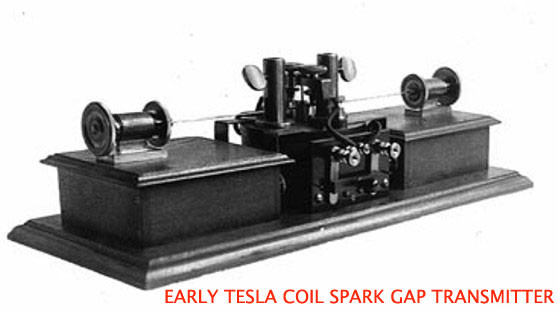
Figure 32. Quenched spark gap. (Tesla at that time pointed out the future of quenching and showed that oscillations can be maintained without a spark being visible to the naked eye between the knobs.) Illustrated in T.C. Martin book, Figs. 135 and 136, p. 211.
"This [Fig. 32] is another improvement in that particular device, which was the weakness of the invention and which I tried to eliminate. This device incorporated many spark gaps in series. It had a peculiar feature; namely, through the great number of gaps, I was able, as I have pointed out in my writings, to produce oscillations without even a spark being visible between the knobs. This device is now known in the art as the "quenched spark gap." Professor Wein has formulated a beautiful theory about it, which I understand has netted him the Nobel prize. Wein's theories are admirable. The only trouble is that he has overlooked one very important fact. It is this: If the apparatus is properly designed and operated, there is no use for the quenched gap, for the oscillations are continuous anyway. The radio men who came after me had the problem before them of making a bell sound, and they immersed it in mercury. Now, you know mercury is heavy. When they struck their bell, the mercury did not permit it to vibrate long because it took away all the energy. I put my bell in a vacuum and make it vibrate for hours. I have designed circuits in connection with an enterprise in 1898 for transmission of energy which, once started, would vibrate three years, and even after that the oscillations could still be detected. Professor Wein's theory is very beautiful, but it really has no practical meaning. It will become useless as soon as the inefficient apparatus of the day, with antennae that radiate energy rapidly, [are] replaced by a scientifically designed oscillator which does not give out energy except when it gets up to a tremendous electromagnetic momentum".

Figure 33. The discharger working in an atmosphere, chiefly consisting of hydrogen, still further weakened by heat. The use of hydrogen in this connection has been claimed as a discovery and patented. Presented in TesIa's lectures before the Franklin Institute and the National Electric Light Association. T.C. Martin book, Fig. 167. pp. 307-308.
"In this form of break [Fig. 33], I changed the atmosphere in which the arc was operating. The atmosphere was mostly hydrogen, and with this device I performed my experiments before the Franklin Institute in Philadelphia and the National Electric Light Association in St. Louis. This has been used by Poulsen and it is now called the "Poulsen arc" and "Poulsen system." But, of course, there is no invention in it. I am on record with prior publications, and besides, the hydrogen does not have any other effect except that it lowers the tension under which the device can operate. It has the disadvantage of producing asymmetrical or distorted waves, and the impulses obtained are not best suited for tuning".

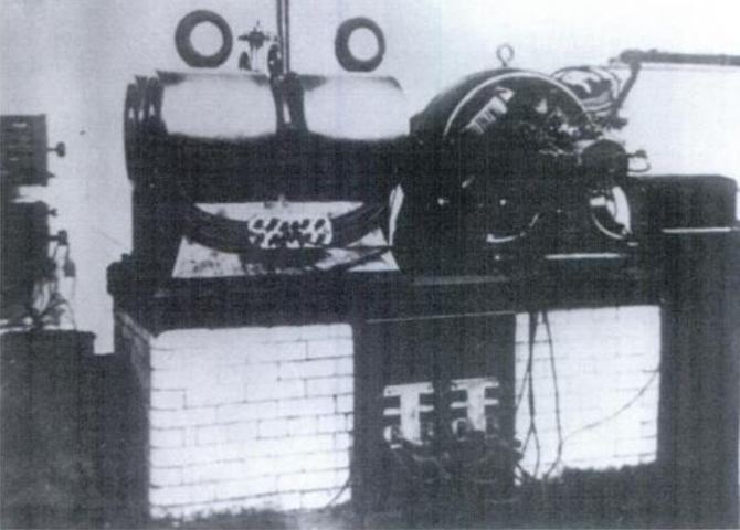
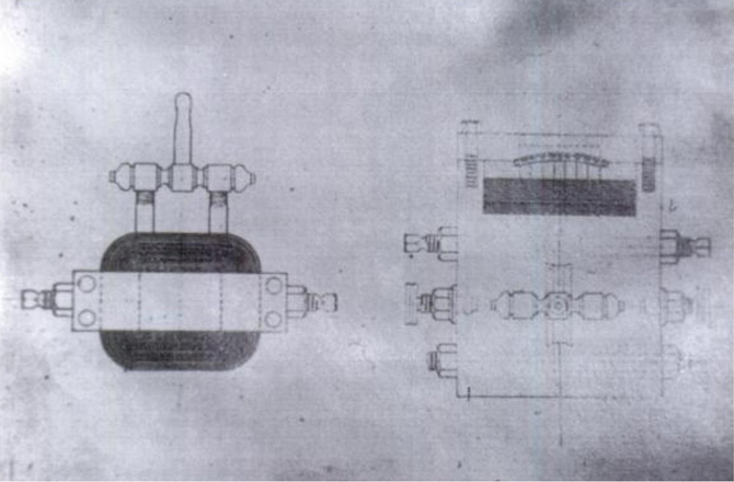
Figure 34. Oscillatory apparatus with interrupter in oil. Exhibited in the Chicago Exposition of 1893 before Helmholtz. Described in U.S. Patent No. 514,168 of February 6, 1894. Application filed August 2, 1893.
"This [Fig. 34] is the apparatus used in the Chicago Exposition of 1893, at which time I explained for the first time to Professor Helmholtz my plan for transmitting energy. After I had shown Professor Helmholtz and other scientific men there certain phenomena, he asked me",
"Now, what is all this intended for?"
"I told him I was trying to develop an apparatus for transmitting energy without wire for telegraphy, telephony, and other purposes. When I explained to Professor Helmholtz the whole idea, I said":
"Excellency, do you think that my plan is realizable?"
He replied,
"Why, certainly it is, but first you must produce the apparatus."
"I started then and there to produce the apparatus".
Counsel:
"Was that conversation at the the Chicago Exposition?"
Tesla:
"Yes. It took place in a pavilion which was built especially for exhibiting my inventions and discoveries. I believe Professor Wedding was there and some other scientists whom I cannot remember now. I showed Professor Helmholtz my vacuum tubes and performed many other experiments".
Counsel:
"Will you describe this apparatus in a little more detail?"
Tesla:
"The apparatus [Fig. 34], as you see, comprised primary and secondary coils immersed in a large tank of oil. The break was automatically effected by means of a turbine. The oil was circulated by a pump, and the current [i.e., stream flow] of oil drove the turbine which effected the make and break. Owing to the fact that the oil used was a very good insulator, rapidly flowing and of great dielectric strength, these make-and-break points were very close together, and the arcs extremely short. The effects were accordingly more intense. Here [T in Diag. 1 of Fig. 34] is a cooler through which the oil was circulated. The oil was forced through the gaps at great speed, and as it flowed out it was supplied again to the tank and the current driving the turbine".
Counsel:
"That device [Diag. 2 of Fig. 34] you call a turbine?"
Tesla:
"Yes. It had vanes like those of a propeller and constituted a rotary break in the circuit".
Counsel:
"What was your prime source [of power]?"
Tesla:
"The primary source was an alternator with a frequency of 133 cycles and, if I recollect rightly, the pressure [at the secondary] was about 20,000 volts. I may have had 10,000 volts. I am not sure what it was, but it must have been certainly from 10,000 to 20,000 volts—within that range".
Counsel:
"I notice you have two sets of transformers in there marked S and S', have you not?"
Tesla:
"This [S'] is my oscillatory circuit. That [S] is the transformer from which the condenser was charged. Here [at S] we had 20,000 volts, or whatever it was, from the commercial transformer and here [at S'] is my secondary which generated the high frequency currents. The rotary gap is shown in detail [Diag. 2 of Fig. 34]".
"I had a special reason for showing this. To meet that great man Helmholtz and other scientific men, and to bring before them for the first time the results of years of previous labor, was an important moment in my life—particularly because Professor Helmholtz gave me the assurance himself that what I explained to him was realizable, provided that I could produce the apparatus. I was very much encouraged".

Figure 35. Apparatus with mechanical break as installed on a large scale in the laboratory at South Fifth Avenue and subsequently at 46 East Houston Street. Described in U.S. Patent No. 645,576 of March 20, 1900. Application filed September 2, 1897.
"This [Fig. 35] is the apparatus I had at 35 South Fifth Avenue and also Houston Street. It shows the whole arrangement as I had it for the demonstration of effects which I investigated.[*] This cable you see [square loop in top half of Fig. 35] is stretched around the hall. These are my condensers. There is the mechanically operated break, and that is a transformer charged from the generator. That is the way I had it for the production of current effects which were rather of damped character because, at that period, I used circuits of great activity which radiated rapidly. In the Houston Street laboratory, I could take in my hands a coil tuned to my body and collect 3/4 horsepower anywhere in the room without tangible connection, and I have often disillusioned my visitors in regard to such wonderful effects. Sometimes, I would produce flames shooting out from my head and run a motor in my hands, or light six or eight lamps. They could not understand these manifestations of energy and thought that it was a genuine transmission of power. I told them that these phenomena were wonderful, but that a system of transmission, based on the same principle, was absolutely worthless. It was a transmission by electromagnetic waves. The solution lay in a different direction. I am showing you this [diagram] simply as a typical form of apparatus of that period, and if you go over the literature of the present day you will find that the newest arrangements have nothing better to show".
Counsel:
"What was the make and break frequency that you got from that apparatus?"
Tesla:
"It was 5,000, 6,000—sometimes higher still. I had two oppositely rotating discs which I will show you and with which I could have reached, probably, 15,000 or 18,000".
Counsel:
"What wave frequencies did you develop?"
Tesla:
"I could operate from a few thousand up to a million per second, if I wanted".
Counsel
"What did you actually use?"
Tesla:
"In these demonstrations, which I showed these effects, these most powerful effects that were the sight of New York at that time, I operated with frequencies from 30,000 to 80,000. At that time I could pick up a wire, coil it up, and tell what the vibration would be, without any test, because I was experimenting day and night".

Figure 36. Isochronous mechanical break used in the laboratory at 35 South Fifth Avenue. Described in U.S. Patent Nos. 568,179 and 568,180 of September 22, 1896. Applications filed July 6 and 9, 1896. (Diagram taken from Patent No. 568,180.)
"This [Fig. 36] is a form of break which I developed in working with alternators. I recognized that it was of tremendous advantage to break at the peak of the wave. If I used just an ordinary break, it would make and break the current at low as well as high points of the wave. Of this apparatus I had two forms; one in which I drove the break right from the shaft of the dynamo and the other in which I drove it with an isochronous motor. Then, by a movement of these knobs (K K), I would make the adjustments so that the makes would occur exactly at the top of the wave. That is a form of break which is embodied in hundreds of patents and used now extensively".

Figure 37. Mechanical break with two oppositely rotating discs used for the purpose of increasing the number of breaks and alternating oscillations practically undamped. (Subsequently patented by others.)
"Here [Fig. 37] I show an apparatus that was installed in the Houston Street laboratory prior to the other break because I wanted to get as high a number of impulses as possible. The drawing dates from the spring of 1896. It is a break with which I could reach from 15,000 to 18,000 interruptions per second. I used it very much until later I found it was not necessary. That is the innocent device which Marconi thought a great invention".
Counsel:
"This is also a rotary gap?"
Tesla:
"Yes, and it consists of two discs of aluminum, with teeth of aluminum on the side. They were rotated by two motors in opposite directions, and as they rotated they alternately closed and opened the circuit. In some instances I used an uneven number of teeth on one and and even number on the other so that I could produce as many breaks as I desired. I will show you later an apparatus more perfect than this one, and of a different kind, in which I have 24 stationary contacts, and 25 rotating elements that established the contact and broke it, so that by one revolution I obtained 24 times 25, or 600 interruptions [per revolution]".
Counsel:
"Whenever you say "the break", you mean "a spark gap"?"
Tesla:
"Yes; otherwise I use the term "circuit controller, preferably".

Figure 38. Use of multi-phase generator with mechanical break. Experiments in the laboratory at 35 South Fifth Avenue and subsequently.
"This [Fig. 38] illustrates another development in a different direction. In order to increase the number of breaks, I employed currents of different phase. I had in my laboratory, permanently, a two-phase dynamo and could get phases between; that is, from two phases, 90 apart, I could obtain four phases, 45 apart. Here is an arrangement shown as I had it, working with three phases [60 apart, and could obtain six phases, 30 apart], and later on I had one with four phases [45 apart, and could obtain eight phases 22 1/2 apart]. You see, as I multiplied the number of the phases, I increased the number of the fundamental discharges".
Counsel:
"What is the date of this apparatus?"
Tesla:
"This I employed already in the 35 South Fifth Avenue laboratory, because I remember that I gave entertainments to several scientific societies and it was then present there. I know on one occasion there was the Society of Architects, and another, the Electrotherapeutic Society, and then I had distinguished men like Mark Twain and Joseph Jefferson—I gave them a demonstration which was published in Martin's article in the Century Magazine of April 1895, and I know that on these occasions I used a two-phase arrangement. Later on I made it four phase. That apparatus existed, therefore, prior to the destruction of my laboratory in 1895".
Counsel:
"Do you recall any publication in which this diagram was illustrated?"
Tesla:
"I made no publication, and I vividly remember that when I installed my apparatus on Long Island I had an arrangement with four transformers and four phases 45 apart. After I had been using this apparatus there, several years afterwards, I ran across a patent, I believe held by the General Electric Company, describing precisely the same arrangement.[*] It was a similar experience as with that patent of Fessenden on the compressed air condenser. Any time I want to use these improvements all I need to do is to produce my records and that will settle the patents".
Counsel:
"When was that drawing [Fig. 38]?"
Tesla:
"This is from an old patent drawing which was made by Mr. Netter".
Counsel:
"But that did not go to patent?"
Tesla:
"No. I have hundreds of inventions that were to be patented but side-stepped. The expense was too great and I could not do it. This form of apparatus with two and four phases was used prior to the destruction of my laboratory in 1895, and it was installed on a large scale with four phases in my plant on Long Island with which I was to telephone around the world, but that is a long story".
Counsel:
"In that use you made of it at your laboratory, was that connected up as shown there [Fig. 38], to an antenna?"
Tesla:
"I used the apparatus, yes, in connection with the antenna too, but this is from a patent drawing in which an antenna is shown; I mean, I used it in every connection. [Fig. 38] illustrates an antenna with my transmitting circuit, but the apparatus was used in all my work, in all my investigations".
Counsel:
"And when this was connected in and used in an antenna, did you use it as in other instances—go off and listen to the notes which you received?"
Tesla:
"Oh, certainly. But I remember that, besides this, I had different kinds of apparatus. Then I had a sensibly damped wave because at that time I still was laboring under the same difficulties as some do this day—I had not learned how to produce a circuit which would give me, with very few fundamental impulses, a perfectly continuous wave. That came with the perfection of the devices. When I came to my experiments in Colorado, I could take my apparatus like that and get a continuous or undamped wave, almost without exception, between individual discharges".
Counsel:
"Speaking of your not having perfectly undamped waves at that time, you were referring to that character of circuit?"
Tesla:
"Yes, but with another kind of circuit I could, of course. The advantage of this apparatus was the delivering of energy at short intervals whereby one could increase activity, and with this scheme I was able to perform all of those wonderful experiments which have been reprinted from time to time in the technical papers. I would take energy out of a circuit at rates of hundreds or thousands of horsepower. In Colorado, I reached 18 million horsepower activities, but that was always by this device: Energy stored in the condenser and discharged in an inconceivably small interval of time. You could not produce that activity with an undamped wave. The damped wave is of advantage because it gives you, with a generator of 1 kilowatt, an activity of 2,000, 3,000, 4,000, or 5,000 kilowatts; whereas, if you have a continuous or undamped wave, 1 kilowatt gives you only wave energy at the rate of 1 kilowatt and nothing more. That is the reason why the system with a quenched gap has become popular".
"I have refined this so that I have been able to take energy out of engines by drawing on their momentum. For instance, if the engine is of 200 horsepower, I take the energy out for a minute interval of time, at a rate of 5,000 or 6,000 horsepower, then I store [it] in a condenser and discharge the same at the rate of several millions of horsepower. That is how these wonderful effects are produced. The condenser is the most wonderful instrument, as I have stated in my writings, because it enables us to attain greater activities than are practical with explosives. There is no limit to the energy which you can develop with a condenser. There is a limit to the energy which you can develop with an explosive".
"A common experiment, for instance, in my laboratory on Houston Street, was to pass through a coil energy at a rate of several thousand horsepower, put a piece of thick tinfoil on a stick, and approach it to that coil. The tinfoil would melt, and would not only melt, but while it was still in that form, it would be evaporated and the whole process took place in so small an interval of time that it was like a cannon shot. Instantly I put it there, there was an explosion. That was a striking experiment. It simply showed the power of the condenser, and at that time I was so reckless that in order to demonstrate to my visitors that my theories were correct, I would stick my head into that coil and I was not hurt; but, I would not do it now".

Figure 39. Apparatus furnishing direct currents of high tension, producing undamped electrical oscillations of high frequency. (This is also shown in [Fig. 27]). Apparatus built in 1895.
"[Fig. 39] shows a four-phase machine which was furnished me by the Westinghouse Electric Company at the close of 1895. My laboratory burned out in May, and I urged my friend, Mr. Albert Schmidt, who was the Superintendent, to give me this alternator as soon as possible. He worked day and night until he got it out, and he certainly did notable work because while the machine was rated at 30 horsepower, I have run it at 150 horsepower".
"By the way, and this is a painful reflection, it was Schmidt and I who developed this type of frame and this general arrangement which is universally adopted now—a base, with the magnets cast below, split at the center line, and a corresponding upper part. That is now used everywhere. I remember years ago, some of my friends, Messrs. Crocker and Wheeler, started with those long magnets and I told them, "The sooner you throw these away and adopt this construction, the better it will be for you." They have got it now; it is all right".
Counsel:
"How is this machine [Fig. 39] shown in connection with that?"
Tesla:
"This dynamo [Fig. 39], you see, is a two-phase machine; that is, I develop from it currents of two-phase. Now, there are four transformers. You see them down here [lower left of Fig. 39] that furnish the primary energy. From these two phases I develop four phases. [However,] this involves something else which I have referred to before; namely, an arrangement which enables me to produce from these alternating currents direct currents and undamped—absolutely undamped—isochronous oscillations of any period I like".
"This is accomplished in the following manner: The secondaries of the four transformers could each develop 44,000 volts. They were specially built for me by the Westinghouse Company. They could, however, be connected in such a way that each would give 11,000 volts, and then I would take these 11,000 volts and these four phases and commutate them by a commutator consisting of aluminum plates, or aluminum segments, which were rotated in synchronism with the alternator. Then I obtained a continuous pressure; that is, direct current of a tension of 44,000 volts, and with these 44,000 volts I charged my condensers. Then by discharging the condensers, either through a stationary gap or through a gap with a mechanical interrupter, I obtained any frequency I desired, and perfectly undamped waves. This arrangement was installed in 1901 in my wireless plant at Long Island, with which I was to telephone around the world".
Counsel:
"Who built that machine?"
Tesla:
"The Westinghouse Company, [under direction of] Mr. Albert Schmidt, Superintendent. It was especially built for me and furnished to my laboratory on Houston Street".
"While I was with the Westinghouse Company, I did two things in addition to bringing my motors to them. I had discovered that Bessemer steel was a much better material for transformers and motors than the soft iron which was previously used. When I came to Pittsburgh, my motors gave results which their motors could not at first produce, and I told them that I had used Bessemer steel. I discovered, in following up the analysis of the steels which were used, that the Bessemer was not steel but really soft iron. The Westinghouse people then adopted my suggestion. At first, Mr. Shallenberger and other electricians there objected very much, but I persuaded them and when the transformers were built we found that we could get 2 1/2 times the output we got before".
"The Westinghouse people kept it a secret for a long time and no one understood how they could make such fine transformers, but all they did was to use the Bessemer steel, on my suggestion, instead of the soft iron the General Electric and other people used. Mr. Westinghouse especially requested me to join efforts with Mr. Schmidt and improve the design of his machines, and we did so. We evolved this design, introduced the ready-made coils, which are pressed on the armature, and other improvements. I took a couple of patents out with Mr. Schmidt, and Mr. Westinghouse was very nice about it. I think he compensated me with $10,000, or something like that, for my suggestions".
Counsel:
"You have spoken of the use of that machine at Houston Street. In what way was it used?"
Tesla:
"I used this machine, as I said, either to produce alternating currents and then interrupt them with a mechanical break at the high peaks of the wave; or, I used alternating currents and interrupted them with an independent rotating break having a great number of teeth. Or, I generated continuous currents by commutating the high tension alternating currents of the transformer. At that time I had two transformers from which I obtained a constant pressure, charged the condenser, and produced undamped waves of any frequency I wanted. As to the machine here [Fig. 39], that is the way it was arranged. It was for the generation of continuous electromotive force and production of undamped waves—from 1895 and on".
Counsel:
"What sort of apparatus was it connected up to for the purpose of absorbing these waves?"
Tesla:
"It was the same as shown here [Fig. 38]. It was connected to the condensers, and these condensers were discharged through a primary which excited the secondary; the antenna was included in the secondary. At other times we discharged the condensers directly so that I could use the antenna without the secondary".
Counsel:
"In the same way did you note the operation of these waves?"
Tesla:
"We did, of course, only in most cases the instrument of reception was different. When I operated with these continuous, or undamped, waves, generated in this way, I usually went to high frequencies. I did operate [at] a very few thousand, but that gave me a smaller output. Such a machine you have to operate at high frequencies to get power".
Counsel:
"What do you mean by high frequencies?"
Tesla:
"I mean frequencies of 30,000, 40,000, 50,000, or something like that".
Counsel:
"And by means of that machine, you put undamped waves of frequency about 50,000 into that antenna at Houston Street in 1895?"
Tesla:
"No, not in 1895. Late in 1895 the machine was furnished and I began to operate in early 1896. That is when I began to operate".
Counsel:
"Then you did this, that I speak of, in 1896?"
Tesla:
"Yes, from 1896 to 1899, right along".
Counsel:
"When you used frequencies like that in your antenna, was your antenna tuned or untuned?"
Tesla:
"I could not use it untuned. That would be absurd".
Counsel:
"What form of device did you use, and where did you use it, for noting the generation of these oscillations or waves in the antenna?"
Tesla:
"I suppose I had hundreds of devices, but the first device that I used, and it was very successful, was an improvement on the bolometer. I met Professor Langley in 1892 at the Royal Institution. He said to me, after I had delivered a lecture, that they were all proud of me. I spoke to him of the bolometer, and remarked that it was a beautiful instrument. I then said",
"Professor Langley, I have a suggestion for making an improvement in the bolometer, if you will embody it in the principle."
"I explained to him how the bolometer could be improved. Professor Langley was very much interested and wrote in his notebook what I suggested. I used what I have termed a small-mass resistance, but of much smaller mass than in the bolometer of Langley, and of much smaller mass than that of any of the devices which have been recorded in patents issued since. Those are clumsy things. I used masses that were not a millionth of the smallest mass described in any of the patents, or in the publications. With such an instrument, I operated, for instance, in West Point—I received signals from my laboratory on Houston Street in West Point".
Counsel:
"This was then the machine that you used when working with West Point?"
Tesla:
"I operated once or twice with it at that distance, but usually as I was investigating in the city. My work at that time was to prepare for the development of a commercial plant, and with me the question was not to transmit signals, but to see what intensity I could get to put me in position to calculate out my apparatus, the dimensions and the forms, before I began the undertaking. It was nothing but preparatory work for the construction of a commercial plant, and I demonstrated its practicability through my experiments, a plant which was to accomplish much more than all others".
Counsel:
"What was the horsepower activity in the oscillating circuits when you used this machine?"
Tesla:
"Usually something like 50 horsepower, and I would get, I should say, approximately 30 horsepower in the antenna; that is, I would get 30 horsepower in the oscillating circuit".
Counsel:
"I understood a little while ago when you made the statement of using several thousand horsepower put into a condenser, you could take out of the condenser a million horsepower. I wondered if you got the same condition with this machine".
Tesla:
"Yes; I charged the condenser with 40,000 volts. When it was charged full, I discharged it suddenly, through a short circuit which gave me a very rapid rate of oscillation. Let us suppose that I had stored in the condenser 10 watts. Then, for such a wave there is a flux of energy of (4 x 10⁴)2, and this is multiplied by the frequency of 100,000. You see, it may go into thousands or millions of horsepower".
Counsel:
"What I wanted to get at was, did that depend upon the suddenness of the discharge?"
Tesla:
"Yes. It is merely the electrical analogue of a pile driver or a hammer. You accumulate energy through a long distance and then you deliver it with a tremendous suddenness. The distance through which the mass moves is small—the pressure immense".
Counsel:
"Did you find that that was the best condition for transmitting energy without the use of wire?"
Tesla:
"No, I did not use that method when I was transmitting energy. I used it only in the production of those freaks for which I have been called a magician. If I had used merely undamped waves, I would have been an ordinary electrician like everybody else".
Counsel:
"You have referred to some delicate receiving instruments. Did you have any trouble with those burning out on account of static?"
Tesla:
"My dear sir, I burned out so many instruments before I discovered what was the matter with them! They burned out instantly until I learned how to make them so that they could not burn out. Yes, that was a great trouble in the beginning".
Counsel:
"Did you succeed in getting them so they would not burn out?"
Tesla:
"Yes. If lightning struck close by, it would not burn out my instrument that has a millionth of the smallest mass used in the instruments of others".
Figure 40. Apparatus and method of conversion by condenser discharges applicable to both alternating and direct currents. Described in lectures before the Franklin Institute and the National Electric Light Association early in 1893. Illustrated in T.C. Martin book, Fig. 165, pp. 302-317.
"This [Fig. 40] is a systematic representation of the various ways which I gave in my lecture before the Franklin Institute and the National Electric Light Association (Light and Other High Frequency Phenomena- A lecture delivered before the Franklin Institute, Philadelphia, February 1893, and before the National Electric Light Association, St. Louis, March, 1893), embodying the general arrangements for the obtainment of continuous waves, undamped or damped waves, from direct and alternating current supply. On the one side [right] you have direct, on the other side alternating current supply. Some electricians have had difficulties in operating some of this apparatus. I had none. I can take an ordinary circuit of 50 volts and produce from it absolutely undamped oscillations and never have the slightest difficulty about it".

Figure 41. Illustrating one of the early experiments with a tuned transformer in the laboratory at South Fifth Avenue.
"Now I come to a few pieces of apparatus which I used in the Houston Street laboratory and the South Fifth Avenue laboratory. I have here [Fig. 41] what you might call a tuning coil. I employed usually another secondary and had my condensers on the table. You see one of the coils in action. This is a tuned circuit which responds to electromagnetic waves which are sent through the room".
Counsel
"This is being used as a receiver of waves?"
Tesla:
"Yes".

Figure 42. Another illustration of one of the early experiments with a tuned transformer in the laboratory at South Fifth Avenue. (Article by T.C. Martin ["Tesla's Oscillator and Other Inventions"], Century Magazine, April 1895, Fig. 9, p. 926.)
"This [instrument shown in Fig. 42] was used in the laboratory on South Fifth Avenue. Here [large circular disc lying on top of coil] is the tuning table with the condensers, a thick primary, and another secondary wire. Sometimes I would operate with two vibrations and I would tune the first circuit to one and the second to the other. Here [referring to cabinets in back of room] you see some of my historical apparatus. Professor Fairfield Osborn[*] came once to my laboratory and said to me, "Why on earth do you keep it in this laboratory?" I had all of this apparatus, 400 pieces, absolutely priceless, and he offered to take it over to the Museum. But I did not heed his advice, and it is gone".
Counsel:
"Where were the waves sent from?"
Tesla:
"The whole room was energized by electromagnetic waves and the receiver responded at any place in the hall. The hall was bigger than this room [shown in Fig. 42], twice as long, and anywhere the intensity of action was the same. These discs [vertical, on top of tuning table] were, I think, about 14 or 15 inches in diameter, and you could see the streamers [shown as white between the discs] anywhere in the room. In a hall twice as long as this, wherever I placed the instrument, it would respond to the electromagnetic waves".
Counsel:
"In this particular instance you are speaking of, the waves were generated right there at 35 South Fifth Avenue?"
Tesla:
"Yes".
Counsel:
"Was that the apparatus in which you had the primaries running entirely around the room?"
Tesla:
"Yes. This was shown to many people and societies".
"This [Fig. 43] shows the first single step I made toward the evolution of an apparatus which, given primary oscillations, will transform them into oscillations capable of penetrating the medium. That experiment, which was marvelous at the time it was performed, was shown for the first time in 1894. I remember the incident perfectly. I called Mr. Edward Adams, the banker, to come and see it, and he was the first man to observe it and to hear my explanation of what it meant".

Figure 43. Apparatus in action illustrating the first step in the evolution of the magnifying transmitter in the laboratory at 35 South Fifth Avenue. (Article by T.C. Martin ["Tesla's Oscillator and Other Inventions"], Century Magazine, April 1895, Fig. 15, p. 932.)
"This coil, which I have subsequently shown in my patents Nos. 645,576 ( System of Transmission of Electrical Energy) and 649,621 ( Apparatus for Transmission of Electrical Energy ), in the form of a spiral, was, as you see, [earlier] in the form of a cone. The idea was to put the coil, with reference to the primary, in an inductive connection which was not close—we call it now a loose coupling—but free to permit a great resonant rise. That was the first single step, as I say, toward the evolution of an invention which I have called my "magnifying transmitter." That means, a circuit connected to ground and to the antenna, of a tremendous electromagnetic momentum and small damping factor, with all the conditions so determined that an immense accumulation of electrical energy can take place".
"It was along this line that I finally arrived at the results described in my article in the Century Magazine of June 1900. [Fig. 43] shows an alternator; not the alternator that was furnished for my laboratory on Houston Street—that was another one, [but] at 35 South Fifth Avenue [and] operated on the same principle. Here [lower left] are the condensers, primary, and all the rest. The discharge there was 5 or 6 feet, comparatively small to what I subsequently obtained. I have produced discharges of 100 feet, and could produce some of 1,000 feet if necessary, with the greatest facility".
Counsel:
"Mr. Tesla, at that point, what did you mean by electro-magnetic momentum?"
Tesla:
"I mean that you have to have in the circuit, inertia. You have to have a large self-inductance in order that you may accomplish two things: First, a comparatively low frequency, which will reduce the radiation of the electromagnetic waves to a comparatively small value, and second, a great resonant effect. That is not possible in an antenna, for instance, of large capacity and small self-inductance. A large capacity and small self-inductance is the poorest kind of circuit which can be constructed; it gives a very small resonant effect. That was the reason why in my experiments in Colorado the energies were 1,000 times greater than in the present antennae".
Counsel:
"You say the energy was 1,000 times greater. Do you mean that the voltage was increased, or the current, or both?"
Tesla:
"Yes [both]. To be more explicit, I take a very large self-inductance and a comparatively small capacity, which I have constructed in a certain way so that the electricity cannot leak out. I thus obtain a low frequency; but, as you know, the electromagnetic radiation is proportionate to the square root of the capacity divided by the self-induction. I do not permit the energy to go out; I accumulate in that circuit a tremendous energy. When the high potential is attained, if I want to give off electromagnetic waves, I do so, but I prefer to reduce those waves in quantity and pass a current into the earth, because electromagnetic wave energy is not recoverable while that [earth] current is entirely recoverable, being the energy stored in an elastic system".
Counsel:
"What elastic system do you refer to?"
Tesla:
"I mean this: If you pass a current into a circuit with large self-induction, and no radiation takes place, and you have a low resistance, there is no possibility of this energy getting out into space; therefore, the impressed impulses accumulate".
Counsel:
"Let's see if I understand this correctly. If you have radiation or electromagnetic waves going from your system, the energy is wasted?"
Tesla:
"Absolutely wasted. From my circuit you can get either electromagnetic waves, 90 percent of electromagnetic waves if you like, and 10 percent in the current energy that passes through the earth. Or, you can reverse the process and get 10 percent of the energy in electromagnetic waves and 90 percent in energy of the current that passes through the earth".
"It is just like this: I have invented a knife. The knife can cut with the sharp edge. I tell the man who applies my invention, you must cut with the sharp edge. I know perfectly well you can cut butter with the blunt edge, but my knife is not intended for this. You must not make the antenna give off 90 percent in electromagnetic and 10 percent in current waves, because the electromagnetic waves are lost by the time you are a few arcs around the planet, while the current travels to the uttermost distance of the globe and can be recovered".
"This view, by the way, is now confirmed. Note, for instance, the mathematical treatise of Sommerfeld,[*] who shows that my theory is correct, that I was right in my explanations of the phenomena, and that the profession was completely misled. This is the reason why these followers of mine in high frequency currents have made a mistake. They wanted to make high frequency alternators of 200,000 cycles with the idea that they would produce electromagnetic waves, 90 percent in electromagnetic waves and the rest in current energy. I only used low alternations, and I produced 90 percent in current energy and only 10 percent in electromagnetic waves, which are wasted, and that is why I got my results". . . .
"You see, the apparatus which I have devised was an apparatus enabling one to produce tremendous differences of potential and currents in an antenna circuit. These requirements must be fulfilled, whether you transmit by currents of conduction, or whether you transmit by electromagnetic waves. You want high potential currents, you want a great amount of vibratory energy; but you can graduate this vibratory energy. By proper design and choice of wave lengths, you can arrange it so that you get, for instance, 5 percent in these electromagnetic waves and 95 percent in the current that goes through the earth. That is what I am doing. Or you can get, as these radio men, 95 percent in the energy of electromagnetic waves and only 5 percent in the energy of the current. . . . The apparatus is suitable for one or the other method. I am not producing radiation with my system; I am suppressing electromagnetic waves. . . . In my system, you should free yourself of the idea that there is radiation, that the energy is radiated. It is not radiated; it is conserved"
7-.Theory and Technique of Energy Transmission

Figure 78. Experimental demonstration in the Houston Street laboratory, before G.D. Seeley, Examiner in Chief, U.S. Patent Office, January 23, 1898, of the practicability of transmission of electrical energy in industrial amounts by the method and apparatus described in U.S. Patents No. 645,576 and No. 649,621. Applications filed September 2, 1897.
Tesla:
"This [Fig. 78] is a diagram representing the arrangement of apparatus as in a practical experiment which I performed before G.D. Seeley, Examiner in Chief, U.S. Patent Office, on the 23rd of January, 1898. This experiment illustrates a great departure I had made a little prior to that date. Up to the end of 1896, I had been developing the wireless system along the lines set forth in my lecture which is in the Martin book, particularly in the chapter on Electrical Resonance, pages 340-349. As I stated then, if that plan of mine was practicable, distance meant absolutely nothing; distance merely came into consideration when you flashed rays, electro-magnetic or Hertzian waves, or some agency of that kind. By the plan I had conceived, if it was realizable, it was just as easy to telegraph or telephone across the entire globe as it is across this room".
"Developing along these lines, my effort was first to have the biggest possible capacity because I had shown that, theoretically, the effect would be dependent upon the quantity of electricity displaced. The quantity of electricity displaced is proportionate to the capacity. Therefore, in order to realize my scheme, it seemed necessary to employ the biggest possible capacities that could be practically constructed; that was my idea at the beginning".
"But I knew also that even with a big capacity, if I connected it to the ground, through a generator, there still would be a frequency high enough to cause a considerable loss of energy in the production of the Hertz or electromagnetic waves; consequently, I had to employ also a very large inductance. Thus, my system was based on the proposition that I employ a very large inductance and a very large capacity and, furthermore, that I raise the potential of the source so high, by resonance, as to displace a quantity of electricity big enough to affect sensibly not only the near portions of the globe, a distance of 100 miles or so, but the whole globe".
"In [my] Houston Street laboratory, I had already satisfied myself that it could be done. But in experimenting with these high potential discharges which I was always producing, I discovered a wonderful thing. I found, namely, that the air, which had been behaving before like an insulator, suddenly became like a conductor; that is, when subjected to these great electrical stresses, it broke down and I obtained discharges which were not accountable for by the theory that the air was an insulator. When I calculated the effects, I concluded that this must be due to the potential gradient at a distance from the electrified body, and subsequently I came to the conviction that it would be ultimately possible, without any elevated antenna -- with very small elevation -- to break down the upper stratum of the air and transmit the current by conduction".
"Having discovered that, I established conditions under which I might operate in putting up a practical commercial plant. When the matter came up in the patents before the Examiner, I arranged this experiment [shown in Fig. 78] for him in my Houston Street laboratory".
"I took a tube 50 feet long, in which I established conditions such as would exist in the atmosphere at a height of about 4 1/2 miles, a height which could be reached in a commercial enterprise, because we have mountains that are 5 miles high; and, furthermore, in the mountainous regions we have often great water power, so that the project of transmitting it, if the plan was rational, would be practicable".
"Then, on the basis of the results I had already obtained, I established those conditions, practically, in my laboratory".
"I used that coil which is shown in my patent application of September 2, 1897 (Patent No. 645,576 of March 20, 1900), the primary as described, the receiving circuit, and lamps in the secondary transforming circuit, exactly as illustrated there".
"And when I turned on the current, I showed that through a stratum of air at a pressure of 135 millimeters, when my four circuits were tuned, several incandescent lamps were lighted".
Counsel:
"What did you use as the source of energy in your primary transmitting circuit, at the time you demonstrated this apparatus to Examiner Seeley?"
Tesla:
"I used a break, a mechanically rotating break, which was charging a condenser 5,000 times a second, as I described in my patent Number 645,576 of March 20, 1900".
Counsel:
"What was the voltage that was generated?"
Tesla:
"The voltage was about 4 million volts".
Counsel:
"You say you used a break, which I understand to be a rotary spark gap. What was the original source of power?"
Tesla:
"The original source of power was an alternator which I employed regularly there, from which I could get about 30 horsepower in ordinary experimentation. It was a machine of a frequency of about 60 cycles".
Counsel:
"And that was connected in circuit with the condenser and a gap in the well-known way of your oscillators?"
Tesla:
"Yes".
Counsel:
"Then you got from that, by means of a rotary gap, about 5,000 sparks?"
Tesla:
"Yes, 5,000 per second, and I transferred [these] to a frequency of 200,000 to 250,000 per second. Pardon me for saying, I had arranged for the Examiner to make this demonstration with a high frequency alternator; but just as the work was pressing I tried it and could not get the necessary tension with it, otherwise I would have used the alternator. But in this other way, I could get the 4 million volts I needed; that is the reason why the experiment was made with this kind of apparatus".
Counsel:
"And you had a wave frequency of what?"
Tesla:
"Between 200,000 and 250,000. That was simply wave frequency; that did not mean anything here because I was transmitting through a conductor. I was not radiating energy into space".
Counsel:
"Was that a glass tube?"
Tesla:
"Yes, 2 or 3 inches in diameter, and joined with rubber. Then there was a pipe that led to the pump, and I had a manometer to show accurately the pressure in the tube. I calculated it so that it corresponded to a definite height of about 5 miles. Because I had mentioned in my patent 5 miles, I did not want to retract that statement. It was simply to show that this was practicable".
"We shall come immediately to something which will put all this in a different light".
"Here [referring to Fig. 79] is the earth. Radio engineers do not realize this truth, but when they do they will immediately get a different view of the whole radio transmission and will design their apparatus accordingly. [I]n fact, they will do exactly what I did. It was a revelation to me".
"The earth is 4,000 miles radius. Around this conducting earth is an atmosphere. The earth is a conductor; the atmosphere above is a conductor, only there is a little stratum between the conducting atmosphere and the conducting earth which is insulating. Now, on the basis of my experiments in my laboratory on Houston Street, the insulating layer of air, which separates the conducting layer of air from the conducting surface of the earth, is shown to scale as you see it here. Those [radii lines] are 60 of the circumference of the earth, and you may notice that faint white line, a little bit of a crack, that extends between those two conductors. Now, you realize right away that if you set up differences of potential at one point, say, you will create in the media corresponding fluctuations of potential. But, since the distance from the earth's surface to the conducting atmosphere is minute, as compared with the distance of the receiver at 4,000 miles, say, you can readily see that the energy cannot travel along this curve and get there, but will be immediately transformed into conduction currents, and these currents will travel like currents over a wire with a return. The energy will be recovered in the circuit, not by a beam that passes along this curve and is reflected and absorbed, because such a thing is impossible, but it will travel by conduction and will be recovered in this [emphasis in original] way. Had I drawn this white line to scale on the basis of my Colorado experiments, it would be so thin that you would have to use a magnifying glass to see it".
Figure 79. Diagram explanatory of the transmission of electrical energy by the method described. First put before Lord Kelvin in the Houston Street laboratory, September 1897.
Counsel
"Will you pardon me for interrupting again. You spoke some time ago about getting all of the energy from your transmitting into your receiving station by this method of yours. I do not understand how you can get all of it".
Tesla
"Oh, that is hardly true; I am speaking as a matter of principle. You never can get all the energy, because there is no such thing as perfect apparatus".
Counsel
"I did not mean it in that sense. I understand that there is, of course, always some loss, but my conception was that when you created the disturbance in the electrical condition of the earth at your transmitting station, that that extended out in all radial directions".
Tesla
"Yes, it did".
Counsel
"And therefore how, at any given station, can you get more than a very small fraction of that energy?"
Tesla
"Pardon me, you are mistaken".
Counsel
"That is what I want you to explain. I must be mistaken, because my conception does not fit in with your statements".
Tesla:
"All right, I will explain that".
"In my first efforts, of course I simply contemplated to disturb effectively the earth, sufficiently to operate instruments. Well, you know you must first learn how to walk before you can fly. As I perfected my apparatus, I saw clearly that I can recover, of that energy which goes in all directions, a large amount, for the simple reason that in the system I have devised, once that current got into the earth it had no chance of escaping, because my frequency was low; hence, the electro-magnetic radiation was low. The potential, the electric potential, is like temperature. We might as well call potential electric temperature. The earth is a vast body. The potential differences in the earth are small, radiation is very small. Therefore, if I pass my current into the earth, the energy of the current is stored there as electromagnetic momentum of the vibrations and is not consumed until I put a receiver at a distance, when it will begin to draw the energy and it will go to that point and nowhere else".
Counsel:
"Why is that, on your theory?"
Tesla
"I will explain it by an analogue".
"Suppose that the earth were an elastic bag filled with water. My transmitter is equivalent to a pump. I put it on a point of the globe, and work my little piston so as to create a disturbance of that water. If the piston moves slowly, so that the time is long enough for the disturbance to spread over the globe, then what will be the result of my working this pump? The result will be that the bag will expand and contract rhythmically with the motions of the piston, you see. So that, at any point of that bag, there will be a rhythmical movement due to the pulsations of the pump".
"That is only, however, when the period is long. If I were to work this pump very rapidly, then I would create impulses, and the ripples would spread in circles over the surface of the globe. The globe will no longer expand and contract in its entirety, but it will be subject to these outgoing, rippling waves".
"Remember, now, that the water is incompressible, that the bag is perfectly elastic, that there are no hysteretic losses in the bag due to these expansions and contractions; and remember also, that there is a vacuum, in infinite space, so that the energy cannot be lost in waves of sound. Then, if I put at a distant point another little pump, and tune it to the rhythmical pulses of the pump at the central plant, I will excite strong vibrations and will recover power from them, sufficient to operate a receiver. But, if I have no pump there to receive these oscillations, if there is nowhere a place where this elastic energy is transferred into frictional energy (we always use in our devices frictional energy -- everything is lost through friction), then there is no loss, and if I have a plant of 1,000 horsepower and I operate it to full capacity, that plant does not take power, it runs idle, exactly as the plant at Niagara. If I do not put any motors or any lamps on the circuit, the plant runs idle. There is a 5,000 horsepower turbine going, but no power is supplied to the turbine except such power as is necessary to overcome the frictional losses".
"Now the vast difference between the scheme of radio engineers and my scheme is this. If you generate electromagnetic waves with a plant of 1,000 horsepower, you are using 1,000 horsepower right along -- whether there is any receiving being done or not. You have to supply this 1,000 horsepower, exactly as you have to supply coal to keep your stove going, or else no heat goes out. That is the vast difference. In my case, I conserve the energy; in the other case, the energy is all lost".
Counsel:
"Mr. Tesla, does that not presuppose that the fluid must be incompressible?"
Tesla:
"I should say so, and electricity, whatever it is, certainly it is incompressible because all our experiments show that".
Counsel:
"Now, if you were giving that a name, what principle would you say was involved by which the radiation loss, where there is no receiver, becomes a gain or a conservation where there is a receiver?"
Tesla:
"There is no radiation in this case. You see, the apparatus which I devised was an apparatus enabling one to produce tremendous differences of potential and currents in an antenna circuit. These requirements must be fulfilled, whether you transmit by currents of conduction, or whether you transmit by electromagnetic waves. You want high potential currents, you want a great amount of vibratory energy; but you can graduate this vibratory energy. By proper design and choice of wave lengths, you can arrange it so that you get, for instance, 5 percent in these electromagnetic waves and 95 percent in the current that goes through the earth. That is what I am doing. Or, you can get, as these radio men, 95 percent in the energy of electromagnetic waves and only 5 percent in the energy of the current. Then you are wondering why you do not get good results. I know why I do not get good results in that way. The apparatus is suitable for one or the other method. I am not producing radiation in my system; I am suppressing electromagnetic waves. But, on the other hand, my apparatus can be used effectively with electromagnetic waves. The apparatus has nothing to do with this new method except that it is the only means to practice it. So that in my system, you should free yourself of the idea that there is radiation, that energy is radiated. It is not radiated; it is conserved".
Counsel:
"Right in that connection, and to illustrate your theory, I would like to know whether you consider that the radiation from any wireless station is wasted or conserved, or whether the effect produced by any of them today is due to this conductive action, so far as it is effective".
Tesla:
"Absolutely -- the effect at a distance is due to the current energy that flows through the surface layers of the earth. That has already been mathematically shown, really, by Sommerfeld. [See editorial note p. 75.] He agrees on this theory; but as far as I am concerned, that is positively demonstrated. For instance, take the Sayville antenna. Professor Zenneck took me out and gave me the particulars. I went over the calculations and found that at 36 kilowatts they were radiating 9 kilowatts in electromagnetic wave energy. They had, therefore, only 25 percent of the whole energy in these waves, and I told Professor Zenneck that this energy is of no effect -- that they produce, by the current, differences of potential in the earth, and these differences of potential are felt in Germany and affect the receiver; but the electromagnetic waves get a little beyond Long Island and are lost".
"I have an idea that [you] will get the best picture of the process in my system of transmission if you will imagine that the earth is a reservoir, say, of fluid under pressure -- that is the potential energy -- and at my plant, operating a distant tuned circuit, I must open a valve and enable that energy to flow in. It is exactly that way. The energy is all conserved, whether it is vibrating or purely potential. Whatever the transmitter does in the receiver, the effect is simply to open a valve, as it were, and permit energy to flow in".
"Now, of course, the hardest thing to understand, if one is not a specialist in that line and has not spent years, as I have, in experiments and thought in that direction, is how can a plant like that be economically operated when we know that there are mountain peaks everywhere? Those peaks are antennae; they are likewise charged. Well, it took me a long time to find that out. To give you an idea, let us take a big, enormous mountain like the peak of Tenerife. That is a big mountain that rises out of the sea and goes up to 17,000 or 18,000 feet. Naturally, that is a tremendous antenna, everybody will think. Without calculating, without passing through the experience I have gone through, you will say that peak alone will take away more energy than all the antennae you can put up all over the world. That is not so.
The peak of Tenerife has no more capacity than something like 100 centimeters [110 picofarads], and it will be charged to a very low potential, whereas my antenna could be charged to a very high potential. I can show that the mountain would not absorb much energy, not 0.0001 percent of that my antenna would. I could put my antenna right close to the peak, and it will take 10,000 times more energy.
You must simply realize that the earth is, so far as it is mechanically looked upon, like a rough ball; but when you look at it electrically, it is a polished ball. Lord Kelvin has already, in his papers on atmospheric electricity, of which he kindly sent me two copies -- he did not stop at sending me one -- grasped that; he considered the distribution of electricity on the globe, and came to the conclusion that the capacity of definite terrestrial areas does not increase sensibly with elevation.
"ou see, the electrical surface density on the highest peaks is not any more than just a fraction of 1 percent greater than on the sea. So that the whole thing, to my mind, appears as a wonderfully providential arrangement, and we can by this means realize things so marvelous that one would be almost afraid to talk about them; and the apparatus -- I do not say that because I am the inventor -- the apparatus is practically the Lamp of Aladdin".
Counsel:
"Is it because the earth is this inelastic mass of electricity that it is the basis for your statement that distance is of no consequence? That is the way I visualize that it is, that if the earth is an inelastic mass or body of electricity, and you set that mass into vibration at any one point, that vibration will extend to the antipodes equally as well as it will to a distance of 200 miles. Is that what you had in mind?"
Tesla
I must first clear away some illusionary ideas. You must first understand certain things. Consider, for instance, the term "resistance." When you think of resistance you imagine, naturally, that you have a long, thin conductor; but remember that while resistance is directly proportionate to length, it is inversely proportionate to the section. It is a quality that depends on a ratio. If you take a small sphere of the same size of a pea, and compare its length with its section, you would find a certain resistance. Now you extend this pea to the size of the earth, and what is going to happen?
While the length increases, say a thousand times or a million times, the section increases with the square of the linear dimensions, so that the bigger this thing is the less resistance it has. Indeed, if the earth were as big as the sun we would still be better off than we are; we could readily telephone from one end of the sun to the other by the system, and the larger the planet the better it would be.
Counsel
Then do I get your idea correctly, that distance is of no importance because of the low resistance due to the large section of the earth?
Tesla
No, pardon me.
Counsel
I cannot quite get that. Why is it that with your system distance cuts no figure?
Tesla
Distance cuts no figure for the reason that there is no fall of potential. Now imagine this: Suppose that the earth, in reality, were a big main, a main of copper, say, that all the copper of the earth would be fused into a big main, and then you will readily see it would not make any difference where you tapped that energy, whether you do it nearby or whether you go 100 miles further, because the resistance of the main is nothing. The resistance of the earth does not come in in this way, but in another way.
These questions are very complex. The resistance is only at the point where you get into the earth with your current. The rest is nothing. Those things will be very difficult to explain without a lot of theoretical stuff, which would be unprofitable, when it is here the object to give a clear idea of the principle and nothing else.

Figure 80. Diagram illustrating one of the many wireless fallacies, taken from a U.S. Patent of Guglielmo Marconi, No. 676,332, June 11, 1901.
This [Fig. 80] illustrates one of the fallacies which the questioning has already brought out. Here is, for instance, an attempt to produce a large capacity, an antenna of very large capacity, by using two concentric cylinders. I have already elucidated this error, but in a different phase. The capacity between those two conductors has absolutely nothing to do with the capacity which enters into the transmission of the energy to a distance. That is purely and entirely a local flux, simply a means of wasting energy. Such errors as this you will find throughout all the technical literature, but this has already been explained in another way.
[Summarizing,] I have already explained the various steps I have set forth in the introduction to this long talk. I have explained how I produced the apparatus giving the requisite oscillations; the second step how I transformed those oscillations into vibratory energy capable of going to a distance; and, furthermore, how I solved another problem, namely, that of the right wavelengths which are effective in the conduction of energy to a distance.
Before I went to Colorado, the one thing which I needed to find out was, how does the current flow through the earth? In my experiments from Houston Street and around New York, I had already learned that the effect is proportionate to the quantity of electricity displaced, and I was in the position to accurately calculate a plant for transmission, for instance, across the Pacific or Atlantic. Those were simple problems; but I could not yet tell how the current passes through the earth, and until I could do that I could not undertake the design of a plant in all these particulars so that it could be a piece of engineering.
I spent 30 years of my work in the design of machinery of all kinds, and have never yet designed a machine which did not do as I expected, and I cannot imagine why it should not because when one calculates the things out on the basis of experimental data, the machine has to work as intended. This is engineering.
Therefore, when my friends offered to back me up for a plant under my patents, I though it was best to devote some time to an investigation, to find out what I needed, in order to have all my data accurately and guarantee that the plant would work.
The law which I discovered in Colorado is wonderful, and it shows that results undreamed of before and of incalculable moment will be obtained as soon as a plant, embodying these principles, is established on a large scale.

Figure 81. Diagram illustrating the mode of propagation of the current from the transmitter over the earth's surface.
To give you an idea, I have prepared a diagram [Fig. 81] illustrating an analogue which will clearly show how the current passes through the globe. You know that in a solar eclipse the moon comes between the sun and the earth, and that its shadow is projected upon the earth's surface. Evidently, in a given moment, the shadow will just touch at a mathematical point, the earth, assuming it to be a sphere.
Let us imagine that my transmitter is located at this point, and that the current generated by it now passes through the earth. It does not pass through the earth in the ordinary acceptance of the term, it only penetrates to a certain depth according to the frequency. Most of it goes on the surface, but with frequencies such as I employ, it will dive a few miles below. It can be mathematically shown that it is immaterial how it passes; the aggregate effect of these currents is as if the whole current passes from the transmitter, which I call the pole, to the opposite point, which I call the antipode.
Assume, then, that here is the transmitter, and imagine that this is the surface of the sea, and that now comes the shadow of the moon and touches, on a mathematical point, the calm ocean. You can readily see that as the surface of the water, owing to the enormous radius of the earth, is nearly a plane, that point where the shadow falls will immediately, on the slightest motion of the shadow downward, enlarge the circle at a terrific rate, and it can be shown mathematically that this rate is infinite. In other words, this half-circle on this side will fly over the globe as the shadow goes down; will first start at infinite velocity to enlarge, and then slower and slower and slower, and as the moon's shadow goes further and further and further, it will get slower and slower until, finally, when the three bodies are on the plane of the ecliptic, right in line one with the other in the same plane, then that shadow will pass over the globe with its true velocity in space. Exactly that same thing happens in the application of my system, and I will show this next.

Figure 82. Diagram illustrating the law governing the passage of the current from the transmitter through the earth, first announced in U.S. Patent No. 787,412 of April 18, 1905. Application filed May 16, 1900. See also J. Erskine-Murray, A Handbook of Wireless Telegraphy, Chapt. 17, pp. 312-330, 1913 edition, published by Crosby Lockwood and Son, London, and Appleton & Company, New York.
"This [Fig. 82] illustrates, on a larger scale, the earth. Here is my transmitter -- mine or anybody's transmitter -- because my system is the system of the day. The only difference is in the way I apply it. They, the radio engineers, want to apply my system one way; I want to apply it in another way".
"This is the circuit energizing the antenna. As the vibratory energy flows, two things happen: There is electromagnetic energy radiated and a current passes into the earth. The first goes out in the form of rays, which have definite properties. These rays propagate with the velocity of light, 300,000 kilometers per second. This energy is exactly like a hot stove. If you will imagine that the cylinder antenna is hot -- and indeed it is heated by the current -- it would radiate out energy of exactly the same kind as it does now. If the system is applied in the sense I want to apply it, this energy is absolutely lost, in all cases most of it is lost. While this electromagnetic energy throbs, a current passes into the globe".
"Now, there is a vast difference between these two, the electromagnetic and current energies. That energy which goes out in the form of rays, is, as I have indicated here [on the diagram of Fig. 82], unrecoverable, hopelessly lost. You can operate a little instrument by catching a billionth part of it but, except this, all goes out into space never to return. This other energy, however, of the current in the globe, is stored and completely recoverable. Theoretically, it does not take much effort to maintain the earth in electrical vibration. I have, in fact, worked out a plant of 10,000 horse-power which would operate with no bigger loss than 1 percent of the whole power applied; that is, with the exception of the frictional energy that is consumed in the rotation of the engines and the heating of the conductors, I would not lose more than 1 percent. In other words, if I have a 10,000 horsepower plant, it would take only 100 horsepower to keep the earth vibrating so long as there is no energy taken out at any other place".
"There is another difference. The electromagnetic energy travels with the speed of light, but see how the current flows. At the first moment, this current propagates exactly like the shadow of the moon at the earth's surface. It starts with infinite velocity from that point, but its speed rapidly diminishes; it flows slower and slower until it reaches the equator, 6,000 miles from the transmitter. At that point, the current flows with the speed of light -- that is, 300,000 kilometers per second. But, if you consider the resultant current through the globe along the axis of symmetry of propagation, the resultant current flows continuously with the same velocity of light".
"Whether this current passing through the center of the earth to the opposite side is real, or whether it is merely an effect of these surface currents, makes absolutely no difference. To understand the concept, one must imagine that the current from the transmitter flows straight to the opposite point of the globe".
"There is where I answer the attacks which have been made on me. For instance, Dr. Pupin has ridiculed the Tesla system. He says",
"The energy goes only in all directions."
"It does not. It goes only in one direction. He is deceived by the size and shape of the earth. Looking at the horizon, he imagines how the currents flow in all directions, but if he would only for a moment think that this earth is like a copper wire and the transmitter on the top of the same, he would immediately realize that the current only flows along the axis of the propagation".
"The mode of propagation can be expressed by a very simple mathematical law, which is, the current at any point flows with a velocity proportionate to the cosecant of the angle which a radius from that point includes with the axis of symmetry of wave propagation. At the transmitter, the cosecant is infinite; therefore, the velocity is infinite. At a distance of 6,000 miles, the cosecant is unity; therefore, the velocity is equal to that of light. This law I have expressed in a patent by the statement that the projections of all zones on the axis of symmetry are of the same length, which means, in other words, as is known from rules of trigonometry, that the areas of all the zones must also be equal. It says that although the waves travel with different velocities from point to point, nevertheless each half wave always includes the same area. This is a simple law, not unlike the one which has been expressed by Kepler with reference to the areas swept over by the radii vectors".
"I hope that I have been clear in this exposition — in bringing to your attention that what I show here is the system of the day, and is my system -- only the radio engineers use my apparatus to produce too much of this electromagnetic energy here, instead of concentrating all their attention on designing an apparatus which will impress a current upon the earth and not waste the power of the plant in an uneconomical process".
Counsel:
"You say radio engineers put too much energy into the radiating part. What, as a matter of fact, according to your conception, is the part of the energy that is received in the receivers in the present system?"
Tesla:
"That has been investigated. Very valuable experiments have been made by Dr. Austin, who has measured the effects at a distance. He has evolved a formula in agreement with the Hertz wave theory, and the energy collected is an absolutely vanishing quantity. It is just enough to operate a very delicate receiver. If it were not for such devices as are now in use, the audion, for instance, nothing could be done. But with the audion, they magnify so that this infinitesimal energy they get is sufficient to operate the receiver. With my system, I can convey to a distant point millions of times the energy they transmit".
Counsel:
"To illustrate my question, take for instance the energy used at Sayville and the reception of that at Nauen. I want to know whether it is your idea that the reception there is due to the earth currents that you have described or to the radiated energy".
Tesla:
"It is far more due to the earth currents than to the radiated energy. I believe, indeed, that the radiated energy alone could not possibly produce the effect across the Atlantic. It is simply because they are incidentally sending a current through the globe -- which they think is their current -- that the receiver is affected. The current produces variations of potential at the earth's surface in Germany; these fluctuations of potential energize the circuit, and by resonance they increase the potential there and operate the receiver. But I do not mean that it is absolutely impossible to use my apparatus and operate with electromagnetic waves across the Atlantic or Pacific. I only say that according to calculations, for instance, which I have made of the Sayville plant, the radiated energy is very small and cannot be operative. I have also calculated the distribution of the charge on the antenna. I am told that the Sayville antenna is without abrupt changes of capacity. It is impossible. There are changes even in a cylindrical antenna; but particularly in that form at Sayville -- there are very abrupt changes".
Counsel:
"What would an engineer have to do to the wireless systems of today in order to produce very little radiation of electromagnetic waves and produce a large amount of these earth currents? What changes would he have to make in the system?"
Tesla:
"He would have to construct and operate the apparatus described in my patents and in my lectures".
Counsel:
"He would have to get very much more inductance in the system than he has today, relatively?"
Tesla:
"It is just like this: In an enterprise of this kind, you have to start with certain fundamental propositions. If you are to build a commercial plant, the question comes up how much money is it to cost. Now, you go to specify before your capitalists the various parts of the plant, and you will find that your machinery and the aerial structure will cost so much. If your capitalists are willing to go deep into their pockets, you can put up a tremendous antenna because, as you know, as I pointed out in 1893, that the effects will be proportionate to the capital invested in that part; but you will find great limits there".
"I designed a plant [Wardenclyffe, referring to Fig. 83] years ago with a large capacity and put it before certain architects. They figured that the antenna would cost $450,000 and I had to modify my plans. As you see, you are limited by cost as to the size of the antenna; that is, you are limited as to the capacity and, furthermore, you have selected the frequency. In order to lower the frequency so that there would be no wasteful radiation of energy, you have to employ a large inductance. You have to employ a capacity as large as permissible, and you must use a large inductance in order that you may reach the low frequency which is economical".
Counsel:
"What low frequency is it that is economical?"
Tesla:
"In a patent which appeared in April 1905, the application of which was filed on May 15, 1900, I have enunciated the law of propagation, which I have explained, and have stated that the frequencies should not be more than 30,000 or 35,000 cycles at most, in order to operate economically".

Figure 83. Improved transmitter described in U.S. Patent No. 1,119,732 of December 1, 1914. Application filed January 18, 1902.
Counsel:
"And would it also be necessary to provide for the high potentials of the order of which you have named in order to insure maximum direct currents and minimum electromagnetic wave radiation?"
Tesla:
"No sir. The currents are proportionate to the potentials which are developed under otherwise equal conditions. If you have an antenna of a certain capacity charged to 100,000 volts, you will get a certain current; charged to 200,000 volts, twice the current. When I spoke of these enormous potentials, I was describing an industrial plant on a large scale because that was the most important application of these principles, but I have also pointed out in my patents that the same principles can be applied to telegraphy and other purposes. That is simply a question of how much power you want to transmit".
Counsel:
"In Colorado, which did you use?"
Tesla:
"I used the so-called Tesla transformer. I did not have the high frequency machine with [me] which I could develop as much energy for the experiments, but with my transformer I could get any amount of energy I needed. That is why I used the transformer".
Counsel:
"Tell me what D P stands for [in Fig. 83]?"
Tesla:
"That is a curved plate. The plate has a large radius of curvature. You see, it is to be borne in mind that, in a general way, electricity will accumulate in the same way as the curvature of the surface has a smaller radius. This is an old truth which has been recognized 200 years ago. The design contemplates an arrangement whereby nowhere is electricity accumulated in excess. I am at a substantially uniform distribution of electricity in this structure, not only in the structure, but along the whole circuit where there is a high potential. This, of course, is simply to illustrate the principles. If you design a machine like that [referring to Fig. 83], it will be very much superior to those now in existence, but I have since that time introduced refinements and can produce very much better results than it would be possible with just exactly that construction".
Counsel:
"You have spoken of the fact that you could use either the alternator or the transformer, and you have illustrated in this diagram [Fig. 83] a condenser at G?"
Tesla:
"Yes".
Counsel:
"And stating, I believe, that that represents to your mind any method of getting continuous waves. I think you said, previously, that you actually used either of these methods at Colorado and still had continuous generation".
Tesla:
"Yes".
Counsel:
"Was the method you used there [in Colorado], a spark? -- an arc? -- or what was the method where you got continuous generation?"
Tesla:
"The method was this: I had a 550-volt current with which I charged the condensers. These condensers I discharged through a primary in the form of an arc, sometimes I also introduced in this arc a mechanical break of several thousand per second. And I obtained a perfectly continuous train of waves as has been described in my patents. The reason why I show the condenser here [Fig. 83] is that that is synonymous with undamped waves. If I had shown the whole apparatus as arranged there, then I might still have damped waves; but whether I use an alternator or some other way of getting energy to that condenser, the condenser is usually there. For instance, if I use an alternator, I shunt its terminals with a condenser in order to magnify the current in the primary. I then tune this circuit to the alternator, and magnify the current in the primary in the ratio of the inductance to the resistance. Therefore, this condenser here stands for either method, and simply means that in this system, as is obvious from the description in the patent, the waves are undamped because high rises of potential would not be obtained otherwise. Whenever I wanted to obtain a high potential, I had to observe these rules in order to force the potential up to that value".


Write a comment
Marino (Monday, 07 January 2019 01:40)
Thank you so much this interview.