 Inventions & Experiments
of Nikola Tesla
Inventions & Experiments
of Nikola Tesla
Comming soon
Alternating Current & the induction motor
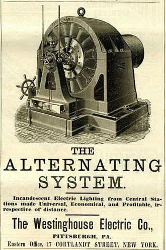
In alternating current (AC), the flow of electric charge periodically reverses direction, whereas in direct current (DC, also dc), the flow of electric charge is only in one direction. The abbreviations AC and DC are often used to mean simply alternating and direct, as when they modify current or voltage.
AC is the form in which electric power is delivered to businesses and residences. The usual waveform of an AC power circuit is a sine wave. In certain applications, different waveforms are used, such as triangular or square waves. Audio and radio signals carried on electrical wires are also examples of alternating current. In these applications, an important goal is often the recovery of information encoded (or modulated) onto the AC signal.
Transmission, distribution, and domestic power supply
AC voltage may be increased or decreased with a transformer. Use of a higher voltage leads to significantly more efficient transmission of power. The power losses (PL) in a conductor are a
product of the square of the current (I) and the resistance (R) of the conductor, described by the formula:

This means that when transmitting a fixed power on a given wire, if the current is doubled, the power loss will be four times greater.
The power transmitted is equal to the product of the current and the voltage (assuming no phase difference); that is:

Thus, the same amount of power can be transmitted with a lower current by increasing the voltage. It is therefore advantageous when transmitting large amounts of power to distribute the power
with high voltages (often hundreds of kilovolts).
However, high voltages also have disadvantages, the main one being the increased insulation required, and generally increased difficulty in their safe handling. In a power plant, power is generated at a convenient voltage for the design of a generator, and then stepped up to a high voltage for transmission. Near the loads, the transmission voltage is stepped down to the voltages used by equipment. Consumer voltages vary depending on the country and size of load, but generally motors and lighting are built to use up to a few hundred volts between phases.
The utilization voltage delivered to equipment such as lighting and motor loads is standardized, with an allowable range of voltage over which equipment is expected to operate. Standard power utilization voltages and percentage tolerance vary in the different mains power systems found in the world.
Modern high-voltage direct-current (HVDC) electric power transmission systems contrast with the more common alternating-current systems as a means for the efficient bulk transmission of electrical power over long distances. HVDC systems, however, tend to be more expensive and less efficient over shorter distances than transformers. Transmission with high voltage direct current was not feasible when Edison, Westinghouse and Tesla were designing their power systems, since there was then no way to economically convert AC power to DC and back again at the necessary voltages.
Three-phase electrical generation is very common. The simplest case is three separate coils in the generator stator that are physically offset by an angle of 120° to each other. Three current waveforms are produced that are equal in magnitude and 120° out of phase to each other. If coils are added opposite to these (60° spacing), they generate the same phases with reverse polarity and so can be simply wired together. In practice, higher "pole orders" are commonly used. For example, a 12-pole machine would have 36 coils (10° spacing). The advantage is that lower speeds can be used. For example, a 2-pole machine running at 3600 rpm and a 12-pole machine running at 600 rpm produce the same frequency. This is much more practical for larger machines.
If the load on a three-phase system is balanced equally among the phases, no current flows through the neutral point. Even in the worst-case unbalanced (linear) load, the neutral current will not exceed the highest of the phase currents. Non-linear loads (e.g., computers) may require an oversized neutral bus and neutral conductor in the upstream distribution panel to handle harmonics. Harmonics can cause neutral conductor current levels to exceed that of one or all phase conductors.
For three-phase at utilization voltages a four-wire system is often used. When stepping down three-phase, a transformer with a Delta (3-wire) primary and a Star (4-wire, center-earthed) secondary is often used so there is no need for a neutral on the supply side.
For smaller customers (just how small varies by country and age of the installation) only a single phase and the neutral or two phases and the neutral are taken to the property. For larger installations all three phases and the neutral are taken to the main distribution panel. From the three-phase main panel, both single and three-phase circuits may lead off.
Three-wire single-phase systems, with a single center-tapped transformer giving two live conductors, is a common distribution scheme for residential and small commercial buildings in North America. This arrangement is sometimes incorrectly referred to as "two phase". A similar method is used for a different reason on construction sites in the UK. Small power tools and lighting are supposed to be supplied by a local center-tapped transformer with a voltage of 55 V between each power conductor and earth. This significantly reduces the risk of electric shock in the event that one of the live conductors becomes exposed through an equipment fault whilst still allowing a reasonable voltage of 110 V between the two conductors for running the tools.
A third wire, called the bond (or earth) wire, is often connected between non-current-carrying metal enclosures and earth ground. This conductor provides protection from electric shock due to
accidental contact of circuit conductors with the metal chassis of portable appliances and tools. Bonding all non-current-carrying metal parts into one complete system ensures there is always a
low electrical impedance path to ground sufficient to carry any fault current for as long as it takes for the system to clear the fault. This low impedance path allows the maximum amount of fault
current, causing the overcurrent protection device (breakers, fuses) to trip or burn out as quickly as possible, bringing the electrical system to a safe state. All bond wires are bonded to
ground at the main service panel, as is the Neutral/Identified conductor if present.
Several inventors competed to be the inventor of the first polyphase system: Tesla, Dolivo-Dobrowolsky, Haselwander, Bradley, Brown, Ferraris, Jonas Wenström, John Hopkinson.
Other links to check:
-
http://twinkle_toes_engineering.home.comcast.net/~twinkle_toes_engineering/induction_motor.htm
-
http://www.eti.kit.edu/english/1390.php
-
http://www.gutenberg.org/files/39272/39272-h/39272-h.htm
-
http://www.gothamcenter.org/blotter/?p=1035
-
http://twinkle_toes_engineering.home.comcast.net/~twinkle_toes_engineering/induction_motor.htm
-
http://www.journal.ftn.kg.ac.rs/Vol_3-2/02-Miljanic.pdf
-
http://www.stealthskater.com/Documents/Tesla_07.pdf
-
http://www.teslauniverse.com/nikola-tesla-books-notebook-from-edison-machine-works-by-nikola-tesla
-
https://electrocrew.wordpress.com/
-
http://electrical-engineering-portal.com/download-center/books-and-guides/electrical-engineering/complete-patents-of-nikola-tesla
-
http://electricalengineerforum.blogspot.com.es/2013/04/nikola-tesla-greatest-electrical.html
-
http://ieee.cincinnati.fuse.net/reiman/05_2001.html
-
http://www.eeh.ee.ethz.ch/uploads/tx_ethstudies/eps_lecture2_power_19.09.08_05.pdf
Write a comment