 Inventions & Experiments
of Nikola Tesla
Inventions & Experiments
of Nikola Tesla
Under construction
Laboratories in New York (1889-1902)
http://mentallandscape.com/Tesla1.htm
http://blog.world-mysteries.com/science/incredible-inventions-of-nikola-tesla/
First Laboratory: 33-35 South Fifth Avenue (1889-1895)
In 1888 Tesla received some fundings from George Westinghouse for his polyphase patents after he introduced his motors and electrical systems in the same year in a classic paper, “A New System of Alternate Current Motors and Transformers” which he delivered before the American Institute of Electrical Engineers.
Many sources suggested that he received $1,000,000, but the most credible record is probablly that Westinhouse paid $60,000. With this money he was able to plan some new experiments and he began to investigate high frequency currents on 1889 in the fourth floor of a six-story building at 33 and 35 South Fifth Avenue in New York City (Tesla's Laboratory Burned - Electrical Review (New York) - March 20, 1895 - p 145).
The first achivements of his research arrived in 1890. He developed a unique new high frequency alternator made up of a steel disk 30 inches in diameter with 384 poles like the teeth of a cog that had zigzag windings on them. The rotor revolved within a fixed stator ring which had another 384 inductor poles. When the motor was operated at 3000 rpm, it produced about 200 volts at 9600 to 10,000 Hz. It was the first device to produce such conditions, but later machines produced high frequencies up to 30,000 Hz (Electromagnetic Waves - Encyclopedia Britannica - 1970 - VIII, p 233).

Experiments with Alternate Currents of Very High Frequency and Their Application to Methods of Artificial Illumination- A lecture delivered before the AIEE, May 20, 1891
"Fig. ? represents the machine used in my experiments before this Institute. The field magnet consists of a ring of wrought iron with 384 pole projections. The armature comprises a steel disc to which is fastened a thin, carefully welded rim of wrought iron. Upon the rim are wound several layers of fine, well annealed iron wire, which, when wound, is passed through shellac. The armature wires are wound around brass pins, wrapped with silk thread. The diameter of the armature wire in this type of machine should not be more than 1/6 of the thickness of the pole projections, else the local action will be considerable".

Nikola Tesla ’s research in the area of wireless telecommunications and alternating current power transmission began in 1888. At the time he was involved in the design and manufacture of rotating
machinery for the fledgling electric power industry. In the course of this work he occasionally had opportunity to run a particular alternator at high speeds (in the area of 10,000 RPM)
developing currents around 2,000 cycles per second, or 2 kHz. The circuits also included, “transformers, etc., and condensers.” The phenomena he observed “were entirely new” and of a nature
leading him to believe that a solution to the problem of wireless energy transmission might be found therein (More info: Inventions, Researches and
Writings of Nikola Tesla, 1894, pp. 152-155; Nikola Tesla On His Work With Alternating Currents and Their Application to Wireless Telegraphy,
Telephony, and Transmission of Power, pp. 1-8).
The Inventions, Researches and Writings of
Nikola Tesla - by Thomas Commerford Martin, Editor:
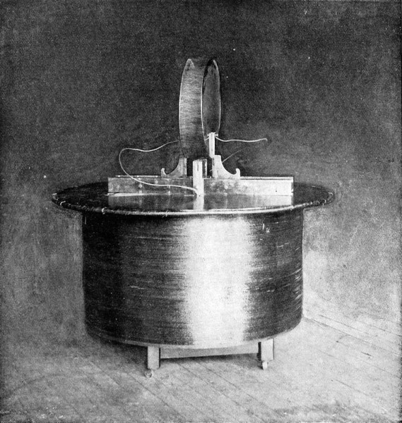
At the outset of his experiments Mr. Tesla encountered great difficulties in the construction of high frequency machines. A generator of this kind is described here, which, though constructed quite some time ago, is well worthy of a detailed description. It may be mentioned, in passing, that dynamos of this type have been used by Mr. Tesla in his lighting researches and experiments with currents of high potential and high frequency, and reference to them will be found in his lectures elsewhere printed in this volume.
[Pg 375]
In the accompanying engravings, Figs. 199 and 200 show the machine, respectively, in side elevation and vertical cross-section; Figs. 201, 202 and 203 showing enlarged details of construction. As will be seen, A is an annular magnetic frame, the interior of which is provided with a large number of pole-pieces D.
Owing to the very large number and small size of the poles and the spaces between them, the field coils are applied by winding an insulated conductor F zigzag through the grooves, as shown in Fig. 203, carrying the wire around the annulus to form as many layers as is desired. In this way the pole-pieces D will be energized with alternately opposite polarity around the entire ring.
For the armature, Mr. Tesla employs a spider carrying a ring J, turned down, except at its edges, to form a trough-like receptacle for a mass of fine annealed iron wires K, which are wound in the groove to form the core proper for the armature-coils. Pins L are set in the sides of the ring J and the coils M are wound over the periphery of the armature-structure and around the pins. The coils M are connected together in series, and these terminals N carried through the hollow shaft H to contact-rings P P, from which the currents are taken off by brushes O.
In this way a machine with a very large number of poles may be constructed. It is easy, for instance, to obtain in this manner three hundred and seventy-five to four hundred poles in a machine that may be safely driven at a speed of fifteen hundred or sixteen hundred revolutions per minute, which will produce ten
[Pg 376]
thousand or eleven thousand alternations of current per second. Arc lamps R R are shown in the diagram as connected up in series with the machine in Fig. 200. If such a current be applied to running arc lamps, the sound produced by or in the arc becomes practically inaudible, for, by increasing the rate of change in the current, and consequently the number of vibrations per unit of time of the gaseous material of the arc up to, or beyond, ten thousand or eleven thousand per second, or to what is regarded as the limit of audition, the sound due to such vibrations will not be audible. The exact number of changes or undulations necessary to produce this result will vary somewhat according to the size of the arc—that is to say, the smaller the arc, the greater the number of changes that will be required to render it inaudible within certain limits. It should also be stated that the arc should not exceed a certain length.
The difficulties encountered in the construction of these machines are of a mechanical as well as an electrical nature. The machines may be designed on two plans: the field may be formed either of alternating poles, or of polar projections of the same polarity. Up to about 15,000 alternations per second in an experimental machine, the former plan may be followed, but a more efficient machine is obtained on the second plan.
In the machine above described, which was capable of running two arcs of normal candle power, the field was composed of a
[Pg 377]
ring of wrought iron 32 inches outside diameter, and about 1 inch thick. The inside diameter was 30 inches. There were 384 polar projections. The wire was wound in zigzag form, but two wires were wound so as to completely envelop the projections. The distance between the projections is about 3/16 inch, and they are a little over 1/16 inch thick. The field magnet was made relatively small so as to adapt the machine for a constant current. There are 384 coils connected in two series. It was found impracticable to use any wire much thicker than No. 26 B. and S. gauge on account of the local effects. In such a machine the clearance should be as small as possible; for this reason the machine was made only 1¼ inch wide, so that the binding wires might be obviated. The armature wires must be wound with great care, as they are apt to fly off in consequence of the great peripheral speed. In various experiments this machine has been run as high as 3,000 revolutions per minute. Owing to the great speed it was possible to obtain as high as 10 amperes out of the machine. The electromotive force was regulated by means of an adjustable condenser within very wide limits, the limits being the greater, the greater the speed. This machine was frequently used to run Mr. Tesla's laboratory lights.

"Courtesy of Tesla Collection." - http://teslacollection.com/
With this kind of alterantors it was possible to work with the basic principles of tuning for first time. Tesla had to tune up the resonance of any device to get the corresponding function. Electrical resonance was theorized at that time but it was primarily a theory that rarely manifested in a practical way. In some experiments the inventor used induction coils to step up the voltage, and he soon found that by removing the iron core, it was possible to improve the output of the coils. In some occasions he also immersed the coils in tanks of boiled linseed oil for better insulation. Today this method is considered a common technique for insulating high voltage and Tesla was probablly one of the firsts electrical engineers to use it. With such discoveries, Tesla could begin with his extensive research on lighting systems using partially evacuated glass tubes which were very similar to the modern neon lights.
Excerpt from My Inventions - Chapter 5:
If my memory serves me right, it was in November, 1890, that I performed a laboratory experiment which was one of the most extraordinary and spectacular ever recorded in the annals of Science. In investigating the behavior of high frequency currents, I had satisfied myself that an electric field of sufficient intensity could be produced in a room to light up electrode less vacuum tubes. Accordingly, a transformer was built to test the theory and the first trial proved a marvelous success. It is difficult to appreciate what those strange phenomena meant at the time. We crave for new sensations, but soon become indifferent to them. The wonders of yesterday are today common occurrences. When my tubes were first publicly exhibited, they were viewed with amazement impossible to describe. From all parts of the world, I received urgent invitations and numerous honors and other flattering inducements were offered to me, which I declined. But in 1892 the demand became irresistible and I went to London where I delivered a lecture before the institution of Electrical Engineers (Experiments with Alternate Currents of High Potential and High Frequency).
During his investigations, Tesla noticed the effects of heating of the high frequency currents and fields and he was the first scientist to suggest the use of radio frequency warming for
therapeutic purposes, also known today as diathermy (Radiation: Biological Effects - Encyclopedia Britannica - 1970 - XVIII, p 1033).
The alternator was usefull for some experiments but the alternations produced were very unreliable and it was necessary for Tesla to produce higher frequencies to develop some of his plans. He stated in a section of an article on alternators (The Inventions Researches and Writings of Nikola Tesla - by Thomas Commerford Martin, Second Edition, New York, Press of Milroy & Emmet, 1894, p 381) :
"The writer will incidentally mention that anyone who attempts for the first time to construct such a machine will have a tale of woe to tell. He will first start out as a matter of course, by making an armature with the required number of polar projections. He will then get the satisfaction of having produced an apparatus which is fit to accompany a thoroughly Wagnerian opera. It may besides possess the virtue of converting mechanical energy into heat in nearly perfect manner."
Tesla decided to search for a more reliable power source. He found that when a capacitor discharges through a coil, the energy oscillates rapidly back and forth between them. This formed the basis of what today we know as the Tesla Coil or also known as the Disruptive Discharge Coil.
A bank of leyden jars or other high voltage condenser is charged by a high voltage induction coil or transformer charges. When the voltage on the condenser builds up to a high enough level, it discharges through a spark gap and a primary coil. The current oscillates at a frequency that may be several million Hertz. A large secondary coil is energized by the primary coil and reaches very high voltages. These first coils were of the same type used with the alternators. They produced arcs about five inches long, indicating a voltage of about 100,000 V was being produced
Between 1891 and 1893, Tesla gave many lectures in America and Europe on his work with alternating current . At these, he demonstrated most of the basic equipment necessary for wireless
telegraphy, such as tuned and coupled free oscillating circuits, the choke coil, and rotary and series spark gapes.
First Work on Wireless Power
Tesla, having invented the method of transmitting power long distances on wires, seemed to want to out do himself when he became fascinated by wireless power. In 1892, just after returning from a
European lecture tour, he decided to experiment with long-range power transmission (Nikola Tesla, "My Inventions: 5. The Magnifying Transmitter", Electrical Experimenter, June 1919, p 173).
Actually he had done some very interesting experiments long before then that probably led up to this. One of the earliest experiments that he performed at his lectures with wireless power
was to set up two large metal plates about 18 feet apart. On a table between these plates were some of his glass tube lamps. When the plates were connected to a powerful oscillator, the tubes lit
up. Tesla first demonstrated this in November of 1890

In Tesla’s laboratory, a similar effect was demonstrated using dynamic magnetic fields instead of electric fields. Built in 1892, the workshop itself was a room 40 feet wide and 80 feet long, with a 12-foot ceiling. Around this room, Tesla ran a cable that was connected to an oscillator (Tesla's Oscillator and Other Inventions - Thomas Commerford Martin - Century - April 1895 - pp 926-927). Secondary coils place in the room would spout sparks when the loop was energized and tuned to their resonant frequency. (See: above)
Although these experiments were amazing for that time, they did not offer a means of transmitting power, and Tesla knew it. They were simply induction effects on a very large scale. Tesla’s first announcement of a possible plan for wireless broadcasting was made in a lecture delivered before the Franklin Institute in Philadelphia on February of 1893 and before the National Electric Light Association in St. Louis on March of the same year. The lecture was entitled “Light and other High-Frequency Phenomena.” In this lecture, a part was included on resonance.
Tesla showed that by using a circuit tuned to resonance, and using very high frequency, only a single wire was necessary for carrying power, with no need for a return conductor. In doing this, a
light or special radio frequency motor would be connected with one terminal to the oscillator and the other to a large metal plate. After demonstrating this, Tesla suggested that since only
one conductor was needed for high frequency, then possibly the earth could be used as that conductor. By learning the resonant frequency of the earth, the transmission of intelligence or even
power could be possible.

In the above diagram used in the lecture, an oscillator S is connected to an elevated plate P, which acts as a reservoir of electricity (condenser), and the ground, which would also act as a reservoir. Any electrical disturbance would create an effect or change in potential in the earth, which could be detected within a certain radius. However, what this radius would be is very hard to tell. Tesla had no idea of what the electrical properties of a huge sphere like the earth would be.
Tesla suggested the use of a trial and error method of finding the earth’s natural period of vibration (if it had one at all). This could be done by using an oscillator of very great power and trying different frequencies to see which one would cause the greatest effect on the surrounding ground.
Since the density of the charge would be very small when distributed over the earth, there would not be much loss, and in theory as Tesla stated:
“It would not require a great amount of energy to produce a disturbance perceptible at great distances, or even all over the surface of the globe.”
Tesla later explained the problem of finding the resonant frequency of the earth. What he had to know was whether the earth behaved like a conductor of finite dimension or as an infinite conductor. He believed that the earth would act much like a wire would in carrying radio frequency electric waves. If the earth acted like an infinite conductor, no resonance effects would exist. As in a wire of infinite length, the waves would travel along the wire with no reflection and no build-up of power. If this were the case with the earth, Tesla’s transmitter would create local vibrations that would vanish and fade into the distance.
However, if the earth acted like a finite conductor, it would have a resonant frequency. The current would travel along the earth until it reached the opposite side and was reflected back. On its way back, the waves would interfere with the oncoming waves and produce interference. If the distance from the transmitter to the opposite side of the earth were equal to one half of the wavelength of the disturbance or any multiple of that, the waves would completely cancel out. If though, the distance is equal to one-quarter wave length or any odd multiple of it, the waves would add together, and a state of resonance would exist.
Naturally, Tesla knew that the earth was finite, but it could have acted as an infinite body due to resistance and its curvature, which might have absorbed the waves before they could be reflected.
The first step toward discovering these facts was to build an oscillator of sufficient strength to disturb the earth’s electrostatic equilibrium. Since Tesla did not keep many notes on his experiments, very little is known about the details of his research. It is known, though, that in the latter part of 1892, he made an important discovery. Up to that time, the disruptive discharge coils bore little resemblance to the well-known Tesla Coils of today. This was because they were built much like regular induction coils, with a multilayered spool for the secondary and the primary wrapped around it. The power and voltage of these devices was limited to the insulation possible with such a configuration.
Tesla found that by making a large coil with a single layer of wire on the secondary, extremely high tension could be produced with ease. Tesla called this the Quarter Wave Coil because the
length of wire in the secondary coil was about equal to a fourth of the wavelength of the oscillation it produced (US645,576 - System of Transmission of Electrical Energy - March 20, 1900 - p 3).
The primary coil, which is only a few turns of heavy cable, is at the base of the secondary and very loosely coupled to it. The base of the secondary is grounded and voltage develops at the upper
terminal instead of both ends as in earlier coils.

A "Tesla" Conical High Frequency, High Potential Oscillator Coil Delivering a Very Powerful Discharge Several Feet in Diameter. The Condensers May Be Seen at Right and Left of Coil, as Well as
50,000 Volt D.C. Dynamo in Foreground.
Using a conical coil, Tesla developed 1,000,000 volts in the spring of 1893 (My Inventions: 5. The Magnifying Transmitter - by Nikola Tesla - Electrical Experimenter - June 1919 - p 173). This coil can be seen in the first photograph (above). A transformer of very high voltage powered it. The condenser is a bank of 32 leyden jars, which can be seen to the left and right of the coil in two banks of 16 each (Mr. Nikola Tesla and His Achievements - by Samuel Cohen - Electrical Experimenter - February 1917 - p 713). The spark gap can be seen to the left of the coil. This was a “quenched gap” made up of a long row of thick copper disks stacked together with small spaces between for the spark. [DPM – a series gap] Behind the coil is an oscillator of the older type, immersed in a wooden oil tank. An ebonite sheet between the two high-tension terminals prevented corona lose.
In 1893, Tesla was involved with Mr. Westinghouse in the design and installation of generators of the polyphase type in a amazing new power plant at Niagara falls. Later in 1894, the Worlds Fair was to be illuminated by alternating current, and both Tesla and Westinghouse were very busy with this. Tesla was given a personal exhibit there, where he demonstrated his AC motors and some of his high frequency discoveries.
My Inventions, Ch. 5 or 6
One day, as I was roaming the mountains, I sought shelter from an approaching storm. The sky became overhung with heavy clouds, but somehow the rain was delayed until, all of a sudden, there was a lightening flash and a few moments after, a deluge. This observation set me thinking. It was manifest that the two phenomena were closely related, as cause and effect, and a little reflection led me to the conclusion that the electrical energy involved in the precipitation of the water was inconsiderable, the function of the lightening being much like that of a sensitive trigger. Here was a stupendous possibility of achievement. If we could produce electric effects of the required quality, this whole planet and the conditions of existence on it could be transformed. The sun raises the water of the oceans and winds drive it to distant regions where it remains in a state of most delicate balance. If it were in our power to upset it when and wherever desired, this might life sustaining stream could be at will controlled. We could irrigate arid deserts, create lakes and rivers, and provide motive power in unlimited amounts. This would be the most efficient way of harnessing the sun to the uses of man. The consummation depended on our ability to develop electric forces of the order of those in nature.
It seemed a hopeless undertaking, but I made up my mind to try it and immediately on my return to the United States in the summer of 1892, after a short visit to my friends in Watford, England; work was begun which was to me all the more attractive, because a means of the same kind was necessary for the successful transmission of energy without wires. At this time I made a further careful study of the Bible, and discovered the key in Revelation. The first gratifying result was obtained in the spring of the succeeding year, when I reaching a tension of about 100,000,000 volts -- one hundred million volts -- with my conical coil, which I figured was the voltage of a flash of lightening. Steady progress was made until the destruction of my laboratory by fire, in 1895, as may be judged from an article by T.C. Martin which appeared in the April number of the Century Magazine. This calamity set me back in many ways and most of that year had to be devoted to planning and reconstruction. However, as soon as circumstances permitted, I returned to the task.

Experiment showing the lighting up of an ordinary incandescent lamp, at a distance, through the influence of electrified ether-waves. (From flash-light photograph.)
---
No one who has witnessed these significant experiments can fail to be impressed with the evidence of the actuality of a medium, call it ether or what you will, which in spite of its wonderful tenuity is as capable of transmitting energy as though it were air or water. Still more impressive to a layman, perhaps, is the confidence and easy precision with which these fine adjustments are brought about.
In Fig. 10 there is a similar coil, in the middle of the same room, which has been so adjusted to the vibrations sent around the shop that an ordinary sixteen-candle-power incandescent lamp is well lighted up.
Tesla's Oscillator and Other Inventions - Century Magazine - Article by T.C. Martin - April 1895, Fig. 9, p. 926:
"Fig. ? pursues this a little further. Above the coil a circle of wire is held by an observer, and an incandescent lamp is attached to the circle. As before, the vibration of the ether in the coil is brought into harmony with the vibrations emitted from the cable. The inductive effect upon the circle held loosely in free space by the observer is so pronounced that the lamp is immediately lighted up, though it may be connected with but one terminal wire, or with two. A 100-volt lamp is used, requiring when employed ordinarily more than one tenth of a horse-power right off the connecting circuit wires direct from the dynamo to bring it up to proper illuminating value. Hence, as will be seen, there is actual proof here of the transmission of at least that amount of energy across a space of some twenty feet and into the bulb by actually no wire at all. This need not surprise us when we remember that on a bright day the ether delivers steadily from the sun a horse-power of energy to every seven square feet of the earth’s surface toward it: so great is its capacity for transmitting energy. Mr. Tesla with his “electrostatic thrusts” has simply learned the knack of loading electrically on the good-natured ether a little of the protean energy of which no amount has yet sufficed to break it down or put it out of temper. We may assume either an enormous speed in what may be called the transmitting wheelwork of the ether, since the weight is inconceivably small; or else that the ether is a mere transmitter of energy by its well-nigh absolute incompressibility".
Nikola Tesla on his work with alternating currents and Their Application to Wireless Telegraphy, Telephony and Transmission of Power: An Extended Interview - Leland I. Anderson, Editor
Now I come to a few pieces of apparatus which I used in the Houston Street laboratory and the South Fifth Avenue laboratory. I have here [Fig. ?] what you might call a tuning coil. I employed usually another secondary and had my condensers on the table. You see one of the coils in action. This is a tuned circuit which responds to electromagnetic waves which are sent through the room.
Counsel
This is being used as a receiver of waves?
Tesla
Yes.
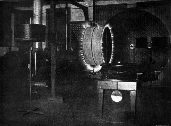
Experiment showing play of electric sparks between condenser plates, produced by electric coil. The coil, standing in the center of a large room, is unconnected with the energizing circuit. (From flash-light photograph.)
---
Tesla's Oscillator and Other Inventions - Century Magazine - Article by T.C. Martin - April 1895, Fig. 9, p. 926:
"A few experiments performed in Mr. Tesla’s laboratory workshop afford an idea of the flexibility of the methods by which powerful electrostatic effects are produced across many feet of intervening space. The workshop is a room about forty by eighty feet, and ten or twelve feet high. A circuit of small cable is carried around it from the terminals of the oscillator. In the center of the clear, open space is placed a coil, wound drum fashion, three or four feet high, and unconnected with the current source save through the medium of the atmosphere. The coil is provided, as shown in the picture, with two condenser plates for adjustment, standing up like cymbals. The plates act after the manner of a spring, and the coil is comparable to an electromagnetic weight. The system of apparatus in the middle of the room has therefore a certain period of vibration, just as though it were a tuning-fork, or a sheet of thin resonant glass. Around the room, over the cable, there are sent from the oscillator electrical current vibrations. By carefully adjusting the condenser plates so that the periodicity or swing of the induced current is brought into step with that of the cable currents, powerful sparks are made to pour across between the plates in the dense streams shown in Fig. 9. In this manner it is easy to reach tensions as high as 200,000 and 300,000 volts".
Nikola Tesla on his work with alternating currents and Their Application to Wireless Telegraphy, Telephony and Transmission of Power: An Extended Interview - Leland I. Anderson, Editor
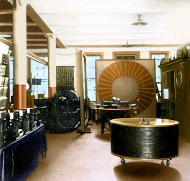
This [instrument shown in Fig. 42] was used in the laboratory on South Fifth Avenue. Here [large circular disc lying on top of coil] is the tuning table with the condensers, a thick primary, and another secondary wire. Sometimes I would operate with two vibrations and I would tune the first circuit to one and the second to the other. Here [referring to cabinets in back of room] you see some of my historical apparatus. Professor Fairfield Osborn[*] came once to my laboratory and said to me, "Why on earth do you keep it in this laboratory?" I had all of this apparatus, 400 pieces, absolutely priceless, and he offered to take it over to the Museum. But I did not heed his advice, and it is gone.
Counsel
Where were the waves sent from?
Tesla
The whole room was energized by electromagnetic waves and the receiver responded at any place in the hall. The hall was bigger than this room [shown in Fig. 42], twice as long, and anywhere the intensity of action was the same. These discs [vertical, on top of tuning table] were, I think, about 14 or 15 inches in diameter, and you could see the streamers [shown as white between the discs] anywhere in the room. In a hall twice as long as this, wherever I placed the instrument, it would respond to the electromagnetic waves.
Counsel
In this particular instance you are speaking of, the waves were generated right there at 35 South Fifth Avenue?
Tesla
Yes.
Counsel
Was that the apparatus in which you had the primaries running entirely around the room?
Tesla
Yes. This was shown to many people and societies.
This [Fig. ?] shows the first single step I made toward the evolution of an apparatus which, given primary oscillations, will transform them into oscillations capable of penetrating the medium. That experiment, which was marvelous at the time it was performed, was shown for the first time in 1894. I remember the incident perfectly. I called Mr. Edward Adams, the banker, to come and see it, and he was the first man to observe it and to hear my explanation of what it meant.
![Apparatus in action illustrating the first step in the evolution of the magnifying transmitter in the laboratory at 35 South Fifth Avenue. (Article by T.C. Martin ["Tesla's Oscillator and Other Inventions"], Century Magazine, April 1895, Fig. 15, p. 932.](https://image.jimcdn.com/app/cms/image/transf/dimension=670x10000:format=jpg/path/s40c423127565d23a/image/i89865cd882ddc9c4/version/1393284851/image.jpg)
A "Tesla" Conical High Frequency, High Potential Oscillator Coil Delivering a Very Powerful Discharge Several Feet in Diameter. The Condensers May Be Seen at Right and Left of Coil, as Well as 50,000 Volt D.C. Dynamo in Foreground.
Article by T.C. Martin - "Tesla's Oscillator and Other Inventions" - Century Magazine, April 1895, Fig. 15, p. 932.
This coil, which I have subsequently shown in my patents Nos. 645,576 and 649,621, in the form of a spiral, was, as you see, [earlier] in the form of a cone. The idea was to put the coil, with reference to the primary, in an inductive connection which was not close -- we call it now a loose coupling -- but free to permit a great resonant rise. That was the first single step, as I say, toward the evolution of an invention which I have called my "magnifying transmitter." That means, a circuit connected to ground and to the antenna, of a tremendous electromagnetic momentum and small damping factor, with all the conditions so determined that an immense accumulation of electrical energy can take place.
It was along this line that I finally arrived at the results described in my article in the Century Magazine of June 1900. [Fig. 43] shows an alternator; not the alternator that was furnished for my laboratory on Houston Street -- that was another one, [but] at 35 South Fifth Avenue [and] operated on the same principle. Here [lower left] are the condensers, primary, and all the rest. The discharge there was 5 or 6 feet, comparatively small to what I subsequently obtained. I have produced discharges of 100 feet, and could produce some of 1,000 feet if necessary, with the greatest facility.
Counsel
Mr. Tesla, at that point, what did you mean by electro-magnetic momentum?
Tesla
I mean that you have to have in the circuit, inertia. You have to have a large self-inductance in order that you may accomplish two things: First, a comparatively low frequency, which will reduce the radiation of the electromagnetic waves to a comparatively small value, and second, a great resonant effect. That is not possible in an antenna, for instance, of large capacity and small self-inductance. A large capacity and small self-inductance is the poorest kind of circuit which can be constructed; it gives a very small resonant effect. That was the reason why in my experiments in Colorado the energies were 1,000 times greater than in the present antennae.
Counsel
You say the energy was 1,000 times greater. Do you mean that the voltage was increased, or the current, or both?
Tesla
Yes [both]. To be more explicit, I take a very large self-inductance and a comparatively small capacity, which I have constructed in a certain way so that the electricity cannot leak out. I thus obtain a low frequency; but, as you know, the electromagnetic radiation is proportionate to the square root of the capacity divided by the self-induction. I do not permit the energy to go out; I accumulate in that circuit a tremendous energy. When the high potential is attained, if I want to give off electromagnetic waves, I do so, but I prefer to reduce those waves in quantity and pass a current into the earth, because electromagnetic wave energy is not recoverable while that [earth] current is entirely recoverable, being the energy stored in an elastic system.
Counsel
What elastic system do you refer to?
Tesla
I mean this: If you pass a current into a circuit with large self-induction, and no radiation takes place, and you have a low resistance, there is no possibility of this energy getting out into space; therefore, the impressed impulses accumulate.
Counsel
Let's see if I understand this correctly. If you have radiation or electromagnetic waves going from your system, the energy is wasted?
Tesla
Absolutely wasted. From my circuit you can get either electromagnetic waves, 90 percent of electromagnetic waves if you like, and 10 percent in the current energy that passes through the earth. Or, you can reverse the process and get 10 percent of the energy in electromagnetic waves and 90 percent in energy of the current that passes through the earth.
It is just like this: I have invented a knife. The knife can cut with the sharp edge. I tell the man who applies my invention, you must cut with the sharp edge. I know perfectly well you can cut butter with the blunt edge, but my knife is not intended for this. You must not make the antenna give off 90 percent in electromagnetic and 10 percent in current waves, because the electromagnetic waves are lost by the time you are a few arcs around the planet, while the current travels to the uttermost distance of the globe and can be recovered.
This view, by the way, is now confirmed. Note, for instance, the mathematical treatise of Sommerfeld,[*] who shows that my theory is correct, that I was right in my explanations of the phenomena, and that the profession was completely misled. This is the reason why these followers of mine in high frequency currents have made a mistake. They wanted to make high frequency alternators of 200,000 cycles with the idea that they would produce electromagnetic waves, 90 percent in electromagnetic waves and the rest in current energy. I only used low alternations, and I produced 90 percent in current energy and only 10 percent in electromagnetic waves, which are wasted, and that is why I got my results.
You see, the apparatus which I have devised was an apparatus enabling one to produce tremendous differences of potential and currents in an antenna circuit. These requirements must be fulfilled, whether you transmit by currents of conduction, or whether you transmit by electromagnetic waves. You want high potential currents, you want a great amount of vibratory energy; but you can graduate this vibratory energy. By proper design and choice of wave lengths, you can arrange it so that you get, for instance, 5 percent in these electromagnetic waves and 95 percent in the current that goes through the earth. That is what I am doing. Or you can get, as these radio men, 95 percent in the energy of electromagnetic waves and only 5 percent in the energy of the current. . . . The apparatus is suitable for one or the other method. I am not producing radiation with my system; I am suppressing electromagnetic waves. . . .In my system, you should free yourself of the idea that there is radiation, that the energy is radiated. It is not radiated; it is conserved.
In the early morning hours of March 13, 1895 a fire broke out and burned everything in the Tesla laboratory.
Second Laboratory: 46 E. Houston Street (1895-1902)
In 1895, on March 13, Tesla was felled by a great tragedy (Tesla's Laboratory Burned - Electrical Review (New York) - March 20, 1895 - p 145). The six story building in which his laboratory was
located burned down. The fourth floor, where his equipment was, collapsed down to the second floor and all his machinery was destroyed. None of it was insured. His lecture equipment, notes,
photographs, and his famous Worlds Fair exhibit were all lost. This, however, was not the greatest loss. Tesla possessed a phenomenal memory and could easily rebuild, and many of his photos were
copied.

Tesla had built ever larger and more powerful oscillators in his Houston Street laboratory. when he constructed one that produced 4,000,000 volts he reached beyond the limits in which high voltage could be handled within a city building.
Courtesy of Rex Hebert - http://www.magnetricity.com/
---
Twain and Tesla became friends in the 1890s, thanks in part to Twain’s lifelong fascination with technology and new inventions. Visiting Tesla’s lab late one night, Twain posed for one of the
first photographs to be lit by incandescent light. In 1895, Tesla and photographer Edward Ringwood Hewett invited Twain back to the lab to pose for another photo, this one lit using an electrical
device called a Crookes tube. When Tesla reviewed the resulting photographic negative, he found it splotchy and spotted and decided it was ruined. It was only weeks later, after German scientist
Wilhelm Röntigen announced his discovery of what he called “X-radiation” produced by Crookes tubes, that Tesla realized the photograph of Twain had been ruined by the X-ray shadows of the
camera’s metal screws.
The Electrical Review in 1896 published X-rays of a man, made by Tesla, with X-ray tubes of his own design. They appeared at the same time as when Roentgen announced his discovery of X-rays. Tesla never attempted to proclaim priority.
In 1887, he worked on a form of X-Rays but much of his research was lost later in the fire at a New York warehouse.
Tesla had originally noticed what he described as "a very special radiation" years earlier when working his "carbon-button" lamp. He produced pictures he called "shadowgraphs" and had performed numerous experiments with them up until the fire at his lab. Upon learning of Röntgen's discovery, Tesla wrote him and sent some of the pictures recovered from the fire. Röntgen replied and asked Tesla how he produced them.
Roentgen congratulated Tesla on his sophisticated X-ray pictures, and Tesla even wrote Roentgen's name on one of his films. He experimented with shadowgraphs similar to those that later were to be used by Wilhelm Rontgen when he discovered X-rays in 1895. Tesla's countless experiments included work on a carbon button lamp, on the power of electrical resonance, and on various types of lightning. Tesla invented the special vacuum tube which emitted light to be used in photography.

Courtesy of Tesla Collection - http://teslacollection.com/
---
Tesla's laboratory at 46 & 48 East Houston Street in New York City. Shown are various laboratory apparatus (note "Egg of Columbus" demonstration device at center). The laboratory is brilliantly illuminated with his high frequency lamps. Circa 1901

Nikola Tesla on his work with alternating currents and Their Application to Wireless Telegraphy, Telephony and Transmission of Power: An Extended Interview - Leland I. Anderson, Editor
Immediately after the destruction of my laboratory by fire, the first thing I did was to design this oscilator (shown in fig. 27). I was still recognizing the absolute necessity of
producing isochronous oscilations, and I could not get it with the alternator, so I constructed this machine. That was all a very expensive piece of work. It comprised four engines. Those four
engines were put in pairs and there was an isochronous controller in the center, and furthermore, that controller was so arranged that I could set two pairs of engines to any phase or produce any
beat I desired. Usually I operated quarter phase ; this is, I generated currents of 90º displacement.
By the way, now, for a first time you see my apparatus om Houston street, which I used for obtaining oscillations, damped and undamped as well . But it was necessary to state that while
others, who had been using my apparatus, but without my experience, have produced with it damped oscillations, my oscillations were almost invariably continuous, or undamped, because my
circuits were so designed that they have a very small damping factor. Even if I operated with very low frequencies, I allways obtained continuous, or undamped, waves for the reason that I
designed my circuits as nonradiative circuits.

In this diagram (Fig. 28) I show the general arrangement of these engines installed in the laboratory at 46 E. Houston Street. There were four, with four vibrating parts installed for furnishing isochronous currents of desired wave frequencies, phases and beats.


Unique Alternating Current Generator or Exciting Tesla's Early "Beat" Receptor. Actuated by Comprest Air or Steam Which Vibrates a Special Diafram-Coil.
---
"That oscillator (Fig. 29) was one of high frequency for isochronous work, and I used it in many ways. The machine, you see, comprised a magnetic frame. The energizing coil, which is removed, produced a strong magnetic field in this region. I calculated the dimensions of the field to make it as intense as possible. There was a powerful tongue of steel which carried a conductor at the extreme end. When it was vibrated, it generated oscillations in the wire. The tongue was so rigid that a special arrangement was provided for giving it a blow; then it would start, and the air pressure would keep it going. The vibrating mechanical system would fall into synchronism with the electrical, and I would get isochronous currents from it. That was a machine of high frequency that emitted a note about like a mosquito. It was something like 4,000 or 5,000. It gave a pitch nearly that of my alternator of the (first) type which I have described.
Of course this device was not intended for a big output, but simply to give me, when operating in connection with receiving circuits, isochronous currents. The excursions of the tongue were so small that one could not see it oscillate, but when the finger was pressed against it the vibration was felt".

This drawing (Fig. 30) shows the construction in detail. Here is the field coil, here are teh conductors in the intense field, the valves for air supply, and the stops for limiting vibration.
The stronger the field was excited, the stronger the vibration became, but just the same, while the amplitude changed, the isochronism was not disturbed.
I want to say now why these machines were the means of obtaining the best results in the wireless work. The machine at the Houston Street laboratory with which I could obtain any difference
of phase, as well as that machine at 35 Soth Fifth Avenue, were the means of running a motor in perfect isochronism. That is, if I connected a synchronous motor to these machines and drove it
with currents of different phase, I obtained an absolutely uniform rotation, constant in time, and when I coupled this motor directly to an alternator, I obtained from the latter currents of
absolutely constant frequency, all the more readily as I tuned the circuit of the alternator to the same frequency.
These machines described in the general way only. The work has covered years, and it would take a long time to explain all about them. They enabled me to operate in whatever I did with
currents of constant frequency, and the small alternators in my experiments were driven in this way. While this work was going on, I was perfecting other ways of generating electric oscillations
of absolutely constant frequency which were then not producible in that art.

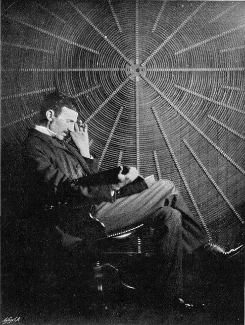
Tesla in his Houston street laboratory. Caption for this photo on electrical review, March 29, 1899, reads: "The operators body in this experiment is charged to a high potential by means of a coil responsive to the waves transmitted to it from a distant oscilator. (Tesla, Master of Lightning Pg.83).


Tesla's model transformer or oscilator in action when creating an effective electrical pressure of 2,5 million volts (resonant wireless transmitting circuit described in Electrical Review, New York, March 29, 1899, pp. 193-197, 204 and Electrical Review, London, May 5, 1899, pp.730-733). The actual width of space traversed by the luminous streams from the single terminal is over sixteen feet. The round "spiderweb" secondary coil is visible in background
---
Picture from Electrical Review, supplement, 26 Oct. 1898. Tesla's laboratory at 46 & 48 East Houston Street in New York City. Shown is a demonstration of his system for the transmission of electrical energy through natural media — a view of his magnifying oscillation transformer in action. Actual width of space traversed by the luminous streamers issuing from the single circular terminal terminating the extra coil is over 16 feet; the area covered is approximately 200 square feet. Estimated pressure is 2 1/2 million volts, the safe limit for this laboratory. It was here that Tesla discovered extraordinary conductive properties of the atmosphere, and to pursue these investigations further he sought to establish an experimental station at a remote location where he would be unrestricted in producing vastly greater voltages. Circa 1896-1898.
Tesla's laboratory at 46 & 48 East Houston Street in New York City, a few blocks south of Washington Square. The New York oscillator is shown in operation. A free standing primary loop and primary capacitors are to the left and rear with the secondary in the background to the right. Circa 1899.
The First "Beat" Receptor for Radio-Telegraphy invented by Tesla, Which Foreshadowed the "Heterodyne."
Tesla used similar types of devices since 1892. He improved the instrument on the photograph at the east of Houston Street Laboratory.
Tesla's most sensitive wireless detector
Tesla Bulbs - The Electrical Experimenter - June, 1919 - Volume VII, No. 74:
"I think it best at this juncture to bring before you a phenomenon, observed by me some time ago, which to the purely scientific investigator may perhaps appear more interesting than any of the results which I have the privilege to present to you this evening. "It may be quite properly ranked among the brush phenomena--in fact, it is a brush, formed at, or near, a single terminal in high vacuum.
In bulbs provided with a conducting terminal, tho it be of aluminum, the brush has but an ephemeral existence, and cannot, unfortunately, be indefinitely preserved in its most sensitive state, even in a bulb devoid of any conducting electrode. In studying the phenomenon, by all means a bulb having no leading-in wire should be used".

Pioneer Radio Engineer Gives Views On Power" - New York Herald Tribune - September 11, 1932:
"The chief object of employing very short waves is to provide an increased number of channels required to satisfy the ever-growing demand for wireless appliances. But this is only because the transmitting and receiving apparatus, as generally employed, is ill-conceived and not well adapted for selection. The transmitter generates several systems of waves, all of which, except one, are useless. As a consequence, only an infinitesimal amount of energy reaches the receiver and dependence is placed on extreme amplification, which can be easily affected by the use of the so-called three-electrode tubes. This invention has been credited to others, but as a matter of fact, it was brought out by me in 1892, the principle being described and illustrated in my lecture before the Franklin Institute and National Electric Light Association (Experiments with Alternate Currents of High Potential and High Frequency). In my original device I put around the incandescent filament a conducting member, which I called a "sieve." This device is connected to a wire leading outside of the bulb and serves to modify the stream of particles projected from the filament according to the charge imparted to it. In this manner a new kind of detector, rectifier and amplifier was provided. Many forms of tubes on this principle were constructed by me and various interesting effects obtained by their means shown to visitors in my laboratory from 1893 to 1899, when I undertook the erection of an experimental world-system wireless plant at Colorado Springs".

The true wireless - by Nikola Tesla -
The Electrical Experimenter -May, 1919 - Volume VII, No. 73:
"My confidence that a signal could be easily flashed around the globe was strengthened thru the discovery of the "rotating brush," a wonderful phenomenon which I have fully described in my address before the Institution of Electrical Engineers, London, in 1892 (Experiments with Alternate Currents of High Potential and High Frequency), and which is illustrated in Fig. 9. This is undoubtedly the most delicate wireless detector known, but for a long time it was hard to produce and to maintain in the sensitive state. These difficulties do not exist now and I am looking to valuable applications of this device, particularly in connection with the high-speed photographic method, which I suggested, in wireless, as well as in wire, transmission."


Comming soon
Other links to check:
- http://www.teslauniverse.com/nikola-tesla-article-teslas-oscillator-and-other-inventions
-
http://blog.world-mysteries.com/science/incredible-inventions-of-nikola-tesla/
Write a comment
saucersource (Saturday, 28 February 2015 15:51)
1937 Nikola Tesla has several secret labs
Reporters questioned Dr. Tesla closely on his report of an interplanetary communication system. He said he had been working in several laboratories, but refused to disclose where they were. Asked if he had a working model of the apparatus, he said "it employs more than three dozen of my inventions, it is a complex apparatus, an agglomeration of parts."
also
Expressing "annoyance" that some newspapers had indicated he would "give a full description" of his atom-smashing tube at yesterday's luncheon, Dr. Tesla said he was bound by financial obligations "involving vast sums of money" against releasing this information.
Nikola Tesla has vast sums of money should be no surprise to
the New York Times as in 1935:
http://www.rastko.rs/projekti/tesla/delo/10896
with $100,000,000 in funding
Nikola Tesla planned a huge project in New Mexico per
references by Mr William R Lyne
http://www.rastko.rs/projekti/tesla/delo/10903
saucersource (Saturday, 28 February 2015 16:10)
Fig 9 Most Sensitive Wireless Detector is devoid of inertia in statement by Nikola Tesla and is forerunner of equipment used in his flying machine or UFOs for that matter as things happen to work out.
saucersource (Sunday, 05 April 2015 14:07)
rastko links do not work but are found at teslaresearch
http://teslaresearch.jimdo.com/articles-interviews/nikola-tesla-at-79-uses-earth-to-transmit-signals-expects-to-have-100-000-000-within-two-years-new-york-world-telegram-july-11-1935/
and
http://teslaresearch.jimdo.com/articles-interviews/sending-of-messages-to-planets-predicted-by-dr-tesla-on-birthday-new-york-times-july-11-1937/