 Inventions & Experiments
of Nikola Tesla
Inventions & Experiments
of Nikola Tesla
Under construction
Tesla coils

The Tesla coil is one of Nikola Tesla's most famous inventions. It is essentially a high-frequency air-core transformer. It takes the output from a 120vAC to several kilovolt transformer & driver circuit and steps it up to an extremely high voltage. Voltages can get to be well above 1,000,000 volts and are discharged in the form of electrical arcs. Tesla himself got arcs up to 100,000,000 volts.
He invented his Tesla Coil around 1891 while he was repeating and then expanding on Heinrich Hertz' experiments that had discovered electromagnetic radiation three years earlier. Tesla decided to power his setup with the high speed alternator he had been developing as part of an improved arc lighting system but found that the high frequency current overheated the iron core and melted the insulation between the primary and secondary windings in the Ruhmkorff coil originally used in Hertz setup. To fix this problem Tesla changed the design so that there was an air gap instead of insulating material between the primary and secondary windings and made it so that the iron core could be moved to different positions in or out of the coil. Tesla also found he needed to put the capacitor normally used in such setups between his alternator and the coil's primary winding to avoid burning out the coil. By adjusting the coil and the capacitor Tesla found he could take advantage of the resonance set up between the two to achieve even higher frequencies.
In Tesla's coil transformer the capacitor, upon break-down of a short spark gap, became connected to a coil of a few turns (the primary winding set), forming a resonant circuit with the frequency of oscillation, usually 20–100 kHz, determined by the capacitance of the capacitor and the inductance of the coil. The capacitor was charged to the voltage necessary to rupture the air of the gap during the input line cycle, about 10 kV by a line-powered transformer connected across the gap. The line transformer was designed to have higher than normal leakage inductance to tolerate the short circuit occurring while the gap remained ionized, or for the few milliseconds until the high frequency current had died away.
The spark gap is set up so that its breakdown occurs at a voltage somewhat less than the peak output voltage of the transformer in order to maximize the voltage across the capacitor. The sudden current through the spark gap causes the primary resonant circuit to ring at its resonant frequency. The ringing primary winding magnetically couples energy into the secondary over several RF cycles, until all of the energy that was originally in the primary has been transferred to the secondary. Ideally, the gap would then stop conducting (quench), trapping all of the energy into the oscillating secondary circuit. Usually the gap reignites, and energy in the secondary transfers back to the primary circuit over several more RF cycles. Cycling of energy may repeat for several times until the spark gap finally quenches. Once the gap stops conducting, the transformer begins recharging the capacitor. Depending on the breakdown voltage of the spark gap, it may fire many times during a mains AC cycle.
A more prominent secondary winding, with vastly more turns of thinner wire than the primary, was positioned to intercept some of the magnetic field of the primary. The secondary was designed to have the same frequency of resonance as the primary using only the stray capacitance of the winding itself to ground and that of any "top hat" terminal placed at the top of the secondary. The lower end of the long secondary coil must be grounded to the surroundings.
The later and higher-power coil design has a single-layer primary and secondary. These Tesla coils are often used by hobbyists and at venues such as science museums to produce long sparks. The American Electrician gives a description of an early Tesla coil wherein a glass battery jar, 15 × 20 cm (6 × 8 in) is wound with 60 to 80 turns of AWG No. 18 B & S magnet wire (0.823 mm²). Into this is slipped a primary consisting of eight to ten turns of AWG No. 6 B & S wire (13.3 mm2) and the whole combination is immersed in a vessel containing linseed or mineral oil.

http://www.tfcbooks.com/mall/more/371tcbg.htm
Before building our first magnifier, it was necessary to master the classic Tesla coil and learn numerous artifices which could later be transferred to the more sophisticated designs. Here, we see the culmination of many Tesla coils built to the classic design, but incorporating many unusual features not often found on such systems. This coil, "Nemesis" is capable of spark outputs of up to 4 times its own 46" secondary coil length! The system uses only .09 ufd capacitance and resonates at 54 kHz. When run to full power potential, it consumes 11-12 kVA of power. The longest spark noted from this system has been 15 feet, point to point.
We see the large classic coil "Nemesis" leaping forward to 12 or 13 feet in a shot from an oblique angle. The power level was only 9 kVA. The sparks constantly impact tool benches and even the system power transformers (lower right)! Notice the large torroid and the rather small 14" x 46" secondary. The secondary is tight wound #18 magnet wire and has an inductance of .11 henry! The primary is 11 turns of 5/8" copper pipe. The coupling is k = .25 which is very tight for a classic Tesla coil system.
http://www.teslascience.org/pages/questions.htm
Tesla placed so much emphasis on finding a solution to one of the most vexing problems of his era—the development of a practical system for wireless telegraphy and telephony. Some preliminary experiments with high-frequency alternators connected to an aerial and ground showed promising results towards this end. He next replaced the alternator with his resonance transformer and achieved even better results. When used as a radio transmitter it was demonstrated that Tesla's oscillator, with its tuned primary and secondary circuits, was able to produce radio waves thousands of times more powerful than the simple spark-coil transmitter used by Heinrich Hertz just a few years before hand—a practical application indeed! (See also: Nikola Tesla On His Work With Alternating Currents and Their Application to Wireless Telegraphy, Telephony, and Transmission of Power).
Patents on Tesla coils
Nikola Tesla in the 1890s pioneered electromagnetic high frequency research. The most accurate record of Tesla’s researches in this period, is contained within his patents. When examining these documents, once should appreciate they were often the result of weeks, months, or in some cases even years of argument with the patent office, and are in consequence deliberate and considered pieces of writing.
To those who are unfamiliar with the life and work of Nikola Tesla, it is probably fair to state he is best remembered as the father of modern electricity, as the pioneer of AC electrical distribution. In this phase of his research he conducted initial tests in the low hundreds of Hertz, and his later high frequency researches with which this article is concerned, were a natural extension of this work.
The first specifically high frequency filing is the Patent US462,418 - Method of and Apparatus for Electrical Conversion and Distribution - November 3, 1891. A document Tesla himself frequently cross referenced, knowing that it was a completely new type of high-frequency lighting system. In it, Tesla states with pride two distinct novelties, firstly the speed of switching obtained, secondly the novel method by which the make and break is made. Tesla had developed a capacitor charge circuit, whereby the voltage in the capacitor accumulated until it was sufficient to break down a dielectric air gap.
The principals cannot really be better illustrated than by reference to the Figure C, an adapted illustration taken directly from the original patent itself. The arrowed circuit path is shown to clarify how the breakdown of the air gap dielectric D, temporarily alters the circuit current path, and routes the accumulated charge through the load(s) G.
There followed a series of other patents developing the device. All of these are for bipolar coils: both ends of the secondary are connected to the working circuit (usually lamps), as opposed to the mono polar format favored by today's basement builders in which the top is connected to a ball or other terminal capacitor, the bottom to ground. The mono polar format emerges later in patents for radio and wireless power, including Tesla's magnifying transmitter.
The patent drawing shows an evolved bipolar coil using tandem chokes to store energy for sudden release into the capacitor, enabling the device to be powered by relatively modest inputs. Chokes are coils wound on iron cores. They store energy as magnetism. When the charging current is interrupted, the magnetic field collapses inducing current in the coils, which rushes in to charge the capacitors.
Based upon a similar set of principals was the patent US454,622 - System of Electric Lighting - June 23, 1891, illustrated directly from the patent in Figure 2. The same novel method of make and break is employed, yet with a step up transformer on the output coils, used to provide high voltage power to florescent lights, or as was also commonly illustrated in later patents, vacuum tubes. In this second patent we clearly see for the very first time all the fundamentals of the ‘Tesla coil.’ This device is a resonant air core transformer, still in use today in the television, radio, automobile, and other industries, to step up a relatively low input voltage, to relatively high output.
US454,622 - System of Electric Lighting - June 23, 1891 (application filed 25 April 1891)
Induction coil PS produces a high secondary voltage which charges condenser C until a spark occurs across air gap a. The discharge current flows through the air gap and the primary of the high-frequency induction coil P'. The discharge of the condenser in this case differs from the discharge through coil with ohmic resistance studied by Henry, already known by that time. In Tesla's oscillator the energy of the high-frequency oscillations in the primary circuit is gradually transferred circuit.
After energizing of the secondary circuit, the remaining energy is returned to the primary, then back to the secondary, and so on until losses reduce it sufficiently to interrupt spark across a in the primary circuit. Then condenser C begins to recharge from source G via induction coil (transformer) PS. Oberbeck published a theoretical analysis of Tesla's oscillator in 1895.
The oscillator converts low-frequency currents into "current of very high frequency and very high potential", which then supplies single-terminal lamps.
The effect Tesla had discovered with this apparatus, was that at around 20 kHz and 20,000v, such a current applied to a bulb, would cause it to light up not in the ordinary fashion Edison pioneered, but rather as a plasma bulb. Today we call such devices florescent lights, and this is the origin of this technology. As was customary, Tesla was ahead of his time, and it is only comparatively recently this technology has found popularity. While the word ‘Tesla coil’ does not directly feature in the patents, the few turn primary and many turn secondary is unmistakable. If there is a central theme to Tesla’s high frequency researches in the 1890s, it is most certainly his beloved Tesla coil, and this is where it first appears, powering florescent lights. In Figure 3 on the left we see the type of equipment Tesla used in his lab to make his transformers.
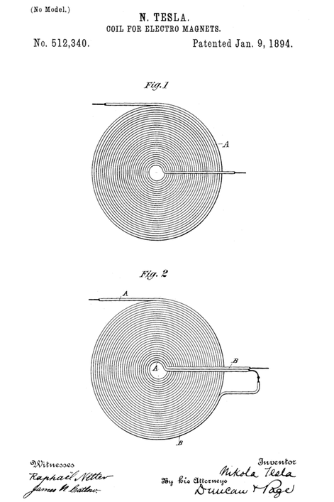
US512,340 - Coil for Electro Magnets - January 9, 1894
The "new idea" of this patent seems to be that inductors have self-capacitance. Unlike an ordinary coil made by turning wire on a tube form, this one uses two wires laid next to each other on a form but with the end of the first one connected to the beginning of the second one. Tesla intended (and stated) these coils will cancel the self-induction, which in common electrical science means the inductive impedance is canceled by capacitive inductance hence it is a self resonant device (it has its own resonant frequency).
Tesla found in its time a way to have a resonant circuit which if properly calculated and constructed, no matter what excited it, it will resonate at the intended frequency. The efficiency of that, as stated in the calculation made within the patent is staggering and the only loss was the resistance of the wire. Less resistance, less loss.
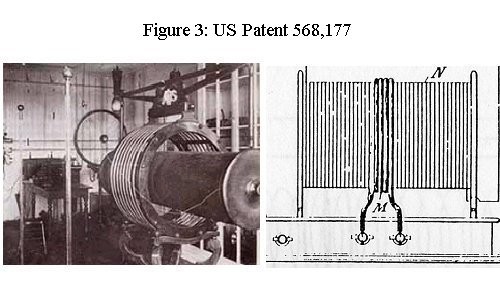
US568,177- Apparatus for Producing Ozone - September 22, 1896.
These two patents US454,622 & US568,177 are especially important, because they help explain where modern ideas of what constitutes a Tesla coil came from. The universally accepted notions of what constitutes a Tesla coil, are derivative from the these two patents, as popularised in part by Lord Kelvin, who visited Tesla’s labs. AC input, capacitor charge, air gap commutation, combined with the classic high voltage air core step up transformer output.
However, a careful reading of the later high frequency patents Tesla filed, reveals the Tesla coil concept in fact underwent substantial development work in the 1890s, and the apparatus Tesla was producing in 1897, was markedly different from the apparatus he was producing in 1892. The later apparatus was in fact DC based over-unity coil pulse apparatus. This was a natural evolution, since the requirements to optimise the back emf discharge effect, are more or less identical to the apparatus and methodology pioneered in the original Tesla coil apparatus.
The 1896 patent drawing shows an evolved bipolar coil using tandem chokes to store energy for sudden release into the capacitor, enabling the device to be powered by relatively modest inputs.
In the case of bipolar coils both ends of the secondary are connected to the working circuit (usually lamps), as opposed to the mono polar format favored by today's basement builders in which the top is connected to a ball or other terminal capacitor, the bottom to ground. The mono polar format emerges later in patents for radio and wireless power, including Tesla's magnifying transmitter.
Chokes are coils wound on iron cores. They store energy as magnetism. When the charging current is interrupted, the magnetic field collapses inducing current in the coils, which rushes in to charge the capacitors.
Pending fig. 3
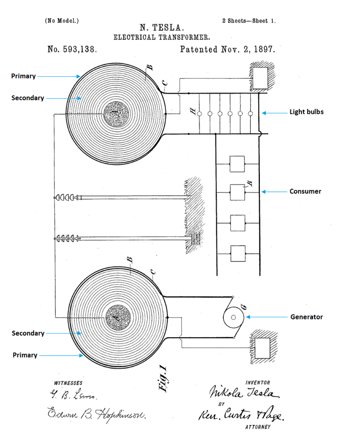
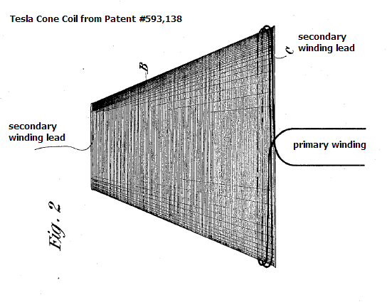
US593,138 - Electrical Transformer - November 2, 1897
A system for the conversion and transmission of electrical energy. In operating various devices with his high-frequency power supply using only one connecting wire he realized the load can placed at some distance from the power supply and still function properly. This is what Tesla called the transmission of electrical energy through one wire without return. Instead of using individual capacitor plates at the transmitting and receiving ends, it is also possible to make a connection directly to the ground. In this case the electrical circuit is completed entirely through the earth itself. The accompanying illustration of a one-wire power transmission system is from Tesla's US593,138 - Electrical Transformer - November 2, 1897 covering the Tesla coil resonance transformer.
Also, the apparatus used in the 1898 Patent Office demonstration at the Houston St. lab involved the transmission of electrical energy in industrial amounts through a rarified medium with ground for return.
US1,119,732 - Apparatus for Transmitting Electrical Energy - December 1, 1914
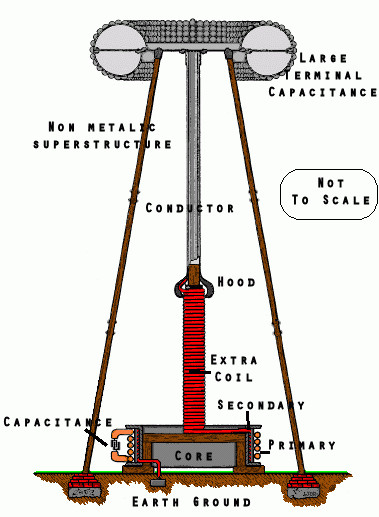
In this patent he no longer speaks of energy broadcast through the upper strata of the atmosphere but of a grounded resonant circuit. Tesla predicted that his magnifying transmitter would prove most important and valuable to future generations, that it would bring about an industrial revolution and make possible great humanitarian achievements.
Solid state Tesla Coil
Comming soon
Other links to check:
- http://www.energeticforum.com/renewable-energy/4628-teslas-mysterious-phantom-streams.html?s=3a857224109d805649f530f1518968ef
- https://www.physicsforums.com/threads/tesla-coil-for-electromagnets.486908/
- http://altered-states.net/barry/tesla/
Write a comment
Cesar (Monday, 04 May 2015 06:29)
Extraordinary! Thank you. I would like to know more about the Solid state Tesla coil.
ryan (Wednesday, 17 January 2018 00:33)
this is useful
Anonymous (Friday, 23 March 2018 05:03)
When was this article made?
Tesla fan (Friday, 07 September 2018 20:03)
This article was very much of use thank u.
miche (Tuesday, 12 February 2019 21:32)
i need more information
Ed (Tuesday, 10 December 2019 02:55)
In teslas method of.signeling. WHY is the capacitor in the second coil have twice the number of plates in it? Is it to change the res. Value or to have one dc and the other a.c.?