 Inventions & Experiments
of Nikola Tesla
Inventions & Experiments
of Nikola Tesla
Under construction
Wireless Transmission of energy
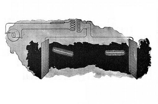
Tesla's wireless house lighting scheme:
- Two high voltage AC plates fill the room with a fairly uniform electric field.
- The bulbs are vertically oriented to align with the electric field.
http://www.frankgermano.net/nikolatesla2.htm - lost source
http://www.tuks.nl/Mirror/frankgermano_net/nikolatesla2.htm
This was the first step towards a practical wireless system. The most striking result obtained – two vacuum tubes lighted in an alternating electrostatic field while held in the hand of the experimenter. The wireless energy transmission effect involved the creation of an electric field between two metal plates, each being connected to one terminal of the induction coil’s secondary winding. Once again, a light-producing device was used as a means of detecting the presence of the transmitted energy.
The ideal way of lighting a hall or room would, however, be to produce such a condition in it that an illuminating device could be moved and put anywhere, and that it is lighted, no matter where it is put and without being electrically connected to anything. I have been able to produce such a condition by creating in the room a powerful, rapidly alternating electrostatic field. For this purpose I suspend a sheet of metal a distance from the ceiling on insulating cords and connect it to one terminal of the induction coil, the other terminal being preferably connected to the ground [type-one]. Or else I suspend two sheets as illustrated in Fig. 29 / 125, each sheet being connected with one of the terminals of the coil [type-two], and their size being carefully determined.
An exhausted tube may then be carried in the hand anywhere between the sheets or placed anywhere, even a certain distance beyond them; it remains always luminous. (Experiments With Alternating Currents of Very High Frequency, and Their Application to Methods of Artificial Illumination by Nikola Tesla - Columbia College, N.Y., May 20, 1891, Inventions, Researches and Writings of Nikola Tesla, pp. 188-189; Nikola Tesla On His Work With Alternating Currents and Their Application to Wireless Telegraphy, Telephony, and Transmission of Power, pp. 7-8)
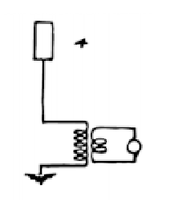
Transmitter type-one: a source consisting of a single metal sheet suspended a distance from the ceiling on insulating cords and connected to one terminal of an induction coil, the other terminal being connected to the ground.
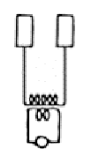
Transmitter type-two: a source consisting of two metal sheets suspended a distance from the ceiling on insulating cords, each sheet being connected with one of the terminals of an induction coil.
Theory of Wireless Transmission
In working to develop an explanation of the two observed effects mentioned above, Tesla recognized that electrical energy could be projected outward into space and detected by a receiving instrument in the general vicinity of the source without a requirement for any interconnecting wires. He went on to develop two theories related to these observations.
- By using two type-one sources positioned at distant points on the earth’s surface, it is possible to induce a flow of electrical current between them.
- By incorporating a portion of the earth as part of a powerful type-two oscillator the disturbance can be impressed upon the earth and detected “at great distance, or even all over the surface of the globe.”
Tesla also made an assumption that Earth is a charged body floating in space.
"A point of great importance would be first to know what is the capacity of the earth? and what charge does it contain if electrified? Though we have no positive evidence of a charged body existing in space without other oppositely electrified bodies being near, there is a fair probability that the earth is such a body, for by whatever process it was separated from other bodies—and this is the accepted view of its origin—it must have retained a charge, as occurs in all processes of mechanical separation".
Tesla was familiar with demonstrations that involved the charging of Leiden jar capacitors and isolated metal spheres with electrostatic influence machines. By bringing these elements into close proximity with each other, and also by making direct contact followed by their separation the charge can be manipulated. He surely had this in mind in the creation of his mental image, not being able to know that the model of Earth’s origin was inaccurate. The presently accepted model of planetary origin is one of accretion and collision.
"If it be a charged body insulated in space its capacity should be extremely small, less than one-thousandth of a farad".
We now know that the earth is, in fact, a charged body, made so by processes—at least in part—related to an interaction of the continuous stream of charged particles called the solar wind that flows outward from the center of our solar system and Earth’s magnetosphere.
"But the upper strata of the air are conducting, and so, perhaps, is the medium in free space beyond the atmosphere, and these may contain an opposite charge. Then the capacity might be incomparably greater".
We also know one of the upper strata of Earth’s atmosphere, the ionosphere, is conducting.
"In any case it is of the greatest importance to get an idea of what quantity of electricity the earth contains".
An additional condition of which we are now aware is that the earth possesses a naturally existing negative charge with respect to the conducting region of the atmosphere beginning at an elevation of about 50 Km. The potential difference between the earth and this region is on the order of 400,000 volts. Near the earth's surface there is a ubiquitous downward directed E-field of about 100 V/m. Tesla referred to this charge as the “electric niveau” or electric level (As noted by James Corum, et al in the paper "Concerning Cavity Q," PROCEEDINGS OF THE 1988 INTERNATIONAL TESLA SYMPOSIUM, and others).
"It is difficult to say whether we shall ever acquire this necessary knowledge, but there is hope that we may, and that is, by means of electrical resonance. If ever we can ascertain at what period the earth's charge, when disturbed, oscillates with respect to an oppositely electrified system or known circuit, we shall know a fact possibly of the greatest importance to the welfare of the human race. I propose to seek for the period by means of an electrical oscillator, or a source of alternating electric currents".
Excerpt from lecture "On light and other high frequency phenomena", delivered before the Franklin Institute, Philadelphia, and the National Electric Light Association, St. Louis, 1893; Inventions, Researches and Writings of Nikola Tesla, 1894, pp. 294-373:
"Assume that a source of alternating currents be connected, as in Fig. 21 / 185, with one of its terminals to earth (conveniently to the water mains) and with the other to a body of large surface P. I think that beyond doubt it is possible to operate electrical devices in a city through the ground or pipe system by resonance from an electrical oscillator located at a central point. But the practical solution of this problem would be of incomparably smaller benefit to man than the realization of the scheme of transmitting intelligence, or perhaps power, to any distance through the earth or environing medium. If this is at all possible, distance does not mean anything. Proper apparatus must first be produced by means of which the problem can be attacked and I have devoted much thought to this subject. I am firmly convinced that it can be done and hope that we shall live to see it done."
Tesla hoped for high-power transmission, which attracted him because, if feasible, this would have eliminated the need for cables to transmit electrical power. Although he suggested some techniques for this, and apparently believed that some kind of resonance could make this possible, his ideas were associated with doubts and controversy, and it seems likely that there was no realistic method for their success. He had no technique for generation of high power microwaves, which could have been transmitted in a focussed beam, and there does not seem to be any basis for supposing that the frequencies which he was able to generate could ever have been used in any point-to-point wireless power distribution system.
However, there is some recent speculative work on very low frequency oscillations which does hint at possibilities of remarkable phenomena involving resonance of the Earth’s structure.
The High Tension Induction Coil
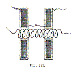
The above described arrangements refer only to the use of commercial coils as ordinarily constructed. If it is desired to construct a coil for the express purpose of performing with it such experiments as I have described, or, generally, rendering it capable of withstanding the greatest possible difference of potential, then a construction as indicated in Fig. 17 / 113 will be found of advantage. The coil in this case is formed of two independent parts which are wound oppositely, the connection between both being made near the primary. The potential in the middle being zero, there is not much tendency to jump to the primary and not much insulation is required. In some cases the middle point may, however, be connected to the primary or to the ground. In such a coil the places of greatest difference of potential are far apart and the coil is capable of withstanding an enormous strain. The two parts may be movable so as to allow a slight adjustment of the capacity effect. (Inventions, Researches and Writings of Nikola Tesla, pp. 172-173)
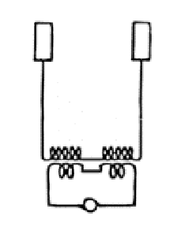
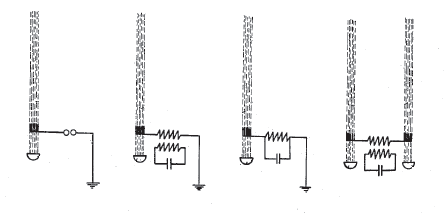
The optimized type-two transmitter consists of two elevated metal plates, each plate being connected to one of the terminals of a Tesla high-tension induction coil.
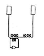
Modification of the optimized type-two transmitter. This circuit is the result of interpolation of the preceding and following diagrams, which are of historical record
---
The modified type-two transmitter shown above consists of two elevated metal plates, each plate being connected to one of the induction coil’s high-voltage terminals. While the coil’s left-hand primary winding remains the same, i.e., it is still closely coupled to the left-hand secondary, the right-hand primary has been removed. This means the right-hand coil is no longer energized by induction. Using Tesla’s terminology, it is now an extra coil. [Some adjustment might be required to bring the extra coil back into resonance with left-hand secondary.] The extra coil is energized or receives energy by one-wire transmission through the interconnecting section of wire.
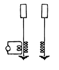
A further modification of a type-two transmitter, this circuit represents the preferred prototype transmitter design developed in 1899 at the Colorado Springs experimental station. The transmitter circuit now consists of separate two elements, an alternator-driven oscillator and an adjacent free oscillatory system.
---
In the further modified type-two transmitter shown above the two halves of the transformer have been physically separated. The transmitter now consists of two discrete units. The oscillator is on the left with its elevated plate still connected to the upper secondary terminal. The free system on the right consists of the original elevated plate connected to the upper terminal of the extra coil. Instead of a wire connecting the lower secondary and lower extra coil terminals, the two coils are now connected to individual earth grounds. These ground connections are constructed so as to introduce the least possible resistance to the earth. In operation a powerful current flows through the subsurface between the two ground terminals. An interaction also takes place between the two elevated terminals. Tesla believed the electrical disturbance would extend to a great distance from the transmitter, possibly across the globe.
The Type-one verses the Type-two Transmitter
http://www.frankgermano.net/nikolatesla2.htm - lost source
http://www.tuks.nl/Mirror/frankgermano_net/nikolatesla2.htm
The question arises as to the cause of the failure reported the 1903 letter to J.B. Morgan. Is the two-coil/two ground concept fundamentally flawed, or was the problem in its’ single-tower implementation? It’s possible the earlier type-two transmitter tests were performed using plant’s chimney-mounted lightning protector as an elevated capacitance in conjunction with the laboratory-side pancake coil, aka the New York oscillator. In this case the tower-side transmitting element would have been a passive extra-coil helical resonator connected to the tower’s cupola and grounding structure. This would have represented a true type-two transmitter, however the amount of power that could have been processed by the alternator-driven oscillator would have been limited by its’ relatively small size.
In the 1925 paper “Wireless power system using the surface of the earth as a conductor,” John B Flowers, H.L. Curtis, J.H. Dillinger, Radio Laboratory, Bureau of Standards, Washington, D.C. [Harnessing the Wheelwork of Nature, pp. 22-23] a statement is made regarding the feasibility of using 60 cycles-per-second as the systems fundamental frequency. An electric generator is connected with wires to ground points 750 miles apart. Although not a true Tesla wireless apparatus, the design does suggest a type-two transmitter.
In 1932 journalist J.J. O’Neill conducted an interview with Tesla in which he makes a distinction between the transmission of electrical energy by atmospheric conduction and earth resonance principles.
I also asked him if he is still at work on the project which he inaugurated in the '90's of transmitting power wirelessly anywhere on earth. He is at work on it, he said, and it could be put into operation. He at that time announced two principles which could be used in this project. In one the ionizing of the upper air would make it as good a conductor of electricity as a metal [using a type-one transmitter]. In the other the power would be transmitted by creating "standing waves" in the earth by charging the earth with a giant electrical oscillator [of the type-two design] that would make the earth vibrate electrically in the same way a bell vibrates mechanically when it is struck with a hammer. "I do not use the plan involving the conductivity of the upper strata of the air," he said, "but I use the conductivity of the earth itself, and in this I need no wires to send electrical energy to any part of the globe." (“Tesla Cosmic Ray Motor May Transmit Power 'Round’ Earth,” Brooklyn Eagle , July 10, 1932, John J. A. O'Neill)
In 1934 the following drawing of a large type-two transmitter appeared in an article on wireless power transmission.
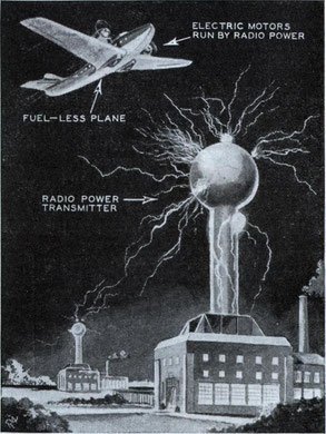
The caption reads, “Nikola Tesla, electrical wizard, foresees the day when airplanes will be operated by radio-transmitted power supplied by ground stations, as shown” (Transmitter type-two, C/S #6; "Radio Power Will Revolutionize the World," Modern Mechanix and Inventions, July 1934, Tesla Said, pp. 261-266)
This suggests that the problem was, in fact, the single-tower implementation, and at some point prior to 1932 Tesla validated the type-two launching structure configuration using two properly spaced top-loaded helical resonators.
One additional observation needs to be made before leaving the subject of the initial Wardenclyffe circuit configuration. Some descriptions of the Wardenclyffe tower include a vertical conductor extending from the bottom of the 120 shaft below the tower up to the under side of the cupola. One account by Anderson on 1969 states:
Excitation currents pulsed through a 16-section telescoping shaft that rose under air pressure 300 feet from the bottom of the well to contact the spherical terminal.
and another by Popovic on 1976:
Radio station on Long Island consisted of a large building and a special antenna tower suspended on a wooden pyramid of several meters in diameter with a changeable height position by means of a metal tube which was telescopically vertically moveable, was emerging from a cylindrical 30 m deep hole in the ground beneath the pyramid.
A direct electrical connection between the elevated isotropic capacitance and the subterranean ground connection would be consistent with the type-two transmitter design. Note that the as-built tower legs were made of wood—not metal—necessitating the conducting shaft. Also, placement of the ground connection at the bottom of the 120-foot excavation might have been a way to partially compensate for height lost in the initial design changes. Tesla’s original plans called for an overall tower height of 600 feet.
The Air-Ground Connection
http://www.teslauniverse.com/nikola-tesla-article-wardenclyffe-today
To properly supply the world’s need for power, it would have taken a series of transmitting towers. The towers’ ground connection is absolutely critical, so there’s a good chance that the majority of the towers would be close to large quantities of salt water. Coastlines and islands such as Hawaii, the British Isles and similar places would have been ideal locations.
Other suitable locations rich in conducting minerals would undoubtedly have been found. Sites of old abandoned copper; silver, gold and mercury mines could have been converted into tower sites. In some cases, steel rails for the ore carts to roll on would have been left in place. They could have been used for additional grounding. Other possible locations include areas abundant with salt such as: Salt Lake City, Bonneville, The Dead Sea, New Orleans and Detroit, Michigan.
Tesla believed that the upper portions of the atmosphere were very conductive for high voltage electricity. It is speculated that Tesla planned to use a high voltage ionizing beam, aided by ultra violet light, to serve as an electrical conduit to the upper regions of the stratosphere. Airplanes and other airships could then draw the necessary current to power their motors. This would have been ideal for zeppelins and blimps. They would have less weight because they would carry little or no fuel. In addition, they would use dependable and light weight electrical motors instead of the heavier and more complicated fuel powered engines.
Good sized ships, yachts and ocean going vessels could have the necessary equipment/apparatus to send up its own ionizing (probably aided by a laser beam) ray to plug into the power grid in the sky.
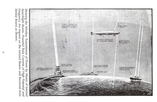
llustrations from an article in the March, 1920 issue of Electrical Experimenter entitled "Wireless Transmission of Power Now Possible". The illustrations show his prototype devices for "directed ionized beam transmissions," a "deathray—searchlight" device. But according to Tesla, the results of tests did not justify the hope of important practical applications in large distance.
"After preliminary laboratory experiments, I made tests on a large scale with the transmitter referred to and a beam of ultra-violet rays of great energy in an attempt to conduct the current to the high rarefied strata of the air and thus create an auroral display such as might be utilized for illumination, especially of oceans at night. I found that there was some virtue in the principal but the results did not justify the hope of important practical applications although, some years later, several inventors claimed to have produced a "death ray" in this manner. While the published reports to this effect were entirely unfounded, I believe that with the new transmitter to be built, many wonders will be achieved".
Principles and concepts of the World Wireless System
Comming soon
Tesla's Flashes Startling - New York Sun - July 17th, 1903:
“It is true that some of them have had to do with wireless telegraphy and that in addition to the tower and poles there is a hole dug in the ground. This is 150 feet deep and is used in these experiments. The people about there, had they been awake instead of asleep, at other times would have seen even stranger things. Some day, but not at this time, I shall make an announcement of something that I never once dreamed of.”
Tesla's New Discovery - New York Sun - January 30th, 1901:
“It is probable that we shall perfect instruments for indicating the altitude of a place by means of a circuit, properly constructed and arranged, and I have thought of a number of other uses to which this principle may be put.”
Different methods for the wireless transmission of energy
Comming soon
Timeline of history of the transmission of wireless energy
http://en.wikipedia.org/wiki/Wireless_power
- 1820: André-Marie Ampère describes Ampere’s law showing that electric current produces a magnetic field.
- 1831: Michael Faraday describes Faraday’s law of induction, an important basic law of electromagnetism.
- 1864: James Clerk Maxwell synthesizes the previous observations, experiments and equations of electricity, magnetism and optics into a consistent theory, andmathematically models the behavior of electromagnetic radiation.
- 1888: Heinrich Rudolf Hertz confirms the existence of electromagnetic radiation. Hertz’s "apparatus for generating electromagnetic waves" is generally acknowledged as the first radio transmitter.
- 1891: Nikola Tesla improves on Hertz's primitive radio-frequency power supply in U.S. Patent No. 454,622, "System of Electric Lighting."
- 1893: Nikola Tesla demonstrates the illumination of phosphorescent bulbs wirelessly (without any wires connected to the bulbs) at the World's Columbian Exposition in Chicago.[citation needed].
- 1894: Hutin & LeBlanc, espouse long held view that inductive energy transfer should be possible, they file a U.S. Patent describing a system for power transfer at 3 kHz.
- 1894: Nikola Tesla wirelessly lights up vacuum tubes at the 35 South Fifth Avenue laboratory, and later at the 46 E. Houston Street laboratory in New York City by means of "electrodynamic induction."
- 1894: Jagdish Chandra Bose ignites gunpowder and rings a bell at a distance using electromagnetic waves, showing that communications signals can be sent without using wires.
- 1895: Jagdish Chandra Bose transmits signals over a distance of nearly a mile.
- 1896: Nikola Tesla transmits signals over a distance of about 48 kilometres (30 mi).
- 1897: Guglielmo Marconi uses Hertz's radio transmitter to transmit Morse code signals over a distance of about 6 km.
- 1897: Nikola Tesla files the first of his patent applications dealing with wireless transmission.
- 1899: In Colorado Springs Nikola Tesla writes, "the inferiority of the induction method would appear immense as compared with the disturbed charge of ground and air method."
- 1900: Guglielmo Marconi fails to get a patent for radio in the United States.
- 1901: Guglielmo Marconi first transmits and receives signals across the Atlantic Ocean using Tesla's wireless transmitter.
- 1902: Nikola Tesla vs. Reginald Fessenden} U.S. Patent Interference No. 21,701. System of Signaling (wireless); selective illumination of incandescent lamps, time and frequency domain spread spectrum telecommunications, electronic logic gates in general.
- 1904: At the St. Louis World's Fair, a prize is offered for a successful attempt to drive a 0.1 horsepower (75 W) air-ship motor by energy transmitted through space at a distance of least 100 feet (30 m).
- 1917: The Wardenclyffe tower is demolished.
- 1926: Shintaro Uda and Hidetsugu Yagi publish their first paper on Uda's "tuned high-gain directional array" better known as the Yagi antenna.
- 1961: William C. Brown publishes article that explores possibilities of microwave power transmission.
- 1964: William C. Brown demonstrated on CBS News with Walter Cronkite a microwave-powered model helicopter that received all the power needed for flight from a microwave beam. Between 1969 and 1975 Brown was technical director of a JPL Raytheon program that beamed 30 kW over a distance of 1 mile at 84% efficiency.
- 1968: Peter Glaser proposes wirelessly transferring solar energy captured in space using "Powerbeaming" technology.
- 1971: Prof. Don Otto develops a small trolley powered by induction at The University of Auckland, in New Zealand.
- 1973: World first passive RFID system demonstrated at Los-Alamos National Lab.
- 1975: Goldstone Deep Space Communications Complex does experiments in the tens of kilowatts.
- 1988: A power electronics group led by Prof. John Boys at The University of Auckland in New Zealand, develops an inverter using novel engineering materials and power electronics and conclude that inductive power transmission should be achievable. A first prototype for a contact-less power supply is built. Auckland Uniservices, the commercial company of The University of Auckland, Patents the Technology.
- 1989: Daifuku, a Japanese company, engages Auckland Uniservices Ltd to develop the technology for car assembly plants and materials handling providing challenging technical requirements including multiplicity of vehicles.
- 1990: Prof. John Boys team develops novel technology enabling multiple vehicles to run on the same inductive power loop and provide independent control of each vehicle. Auckland UniServices Patents the technology.
- 1996: Auckland Uniservices develops an Electric Bus power system using Inductive Power Transfer to charge (30-60kW) opportunistically commencing implementation in New Zealand. Prof John Boys Team commission 1st commercial IPT Bus in the world at Whakarewarewa, in New Zealand.
- 2004: Inductive Power Transfer used by 90 per cent of the US$1 billion clean room industry for materials handling equipment in semiconductor, LCD and plasma screen manufacture.
- 2005: Prof Boys' team at The University of Auckland, refines 3-phase IPT Highway and pick-up systems allowing transfer of power to moving vehicles in the lab
- 2007: A physics research group, led by Prof. Marin Soljačić, at MIT confirm the earlier (1980's) work of Prof. John Boys by wireless powering of a 60W light bulb with 40% efficiency at a 2 metres (6.6 ft) distance using two 60 cm-diameter coils.
- 2008: Bombardier offers new wireless transmission productPRIMOVE, a power system for use on trams and light-rail vehicles.
- 2008: Industrial designer Thanh Tran, at Brunel University made a wireless light bulb powered by a high efficiency 3W LED.
- 2008: Intel reproduces Nikola Tesla's 1894 implementation and Prof. John Boys group's 1988's experiments by wirelessly powering a light bulb with 75% efficiency.
- 2008: Greg Leyh and Mike Kennan of the Nevada Lightning Laboratory publish a paper on the disturbed charge of ground and air method of wireless power transmission with circuit simulations and test results showing an efficiency greater than can be obtained using the electrodynamic induction method.
- 2009: Powermat Technologies introduced wireless charging systems, that work with a combination of radio-frequency identification (RFID) and electromagnetic induction.
- 2009: Palm (now a division of HP) launches the Palm Pre smartphone with the Palm Touchstone wireless charger.
- 2009: A Consortium of interested companies called the Wireless Power Consortium announce they are nearing completion for a new industry standard for low-power (which is eventually published in August 2010) inductive charging.
- 2009: An Ex approved Torch and Charger aimed at the offshore market is introduced. This product is developed by Wireless Power & Communication, a Norway based company.
- 2009: A simple analytical electrical model of electrodynamic induction power transmission is proposed and applied to a wireless power transfer system for implantable devices.
- 2009: Lasermotive uses diode laser to win $900k NASA prize in power beaming, breaking several world records in power and distance, by transmitting over a kilowatt more than several hundred meters.
- 2009: Sony shows a wireless electrodynamic-induction powered TV set, 60 W over 50 cm
- 2010: Haier Group debuts “the world's first” completely wireless LCD television at CES 2010 based on Prof. Marin Soljacic's follow-up research on the 1894 electrodynamic induction wireless energy transmission method and the Wireless Home Digital Interface (WHDI).
- 2010: System On Chip (SoC) group in University of British Columbia develops a highly efficient wireless power transmission systems using 4-coils. The design is optimized for implantable applications and power transfer efficiency of 82% is achieved.
- 2012: A group at University of Toronto, presented for the first time a closed form analytical solution for the optimum load that achieves the maximum possible wireless power transfer efficiency under arbitrary input impedance conditions based on the general two-port parameters of the network. The proposed method effectively decoupled the design of the inductive coupling two-port from the problem of loading and power amplifier design.
- 2012: "Bioelectromagnetics and Implantable Devices" group in University of Utah, USA develops an efficient resonance based wireless power and data transfer system for biomedical Implants. Presented design achieves more than twice the efficiency and frequency bandwidth compared to conventional inductive link approach. Design approach is extendable to other industrial "smart" wireless power transfer system.
- 2012: Christopher Tucker, Kevin Warwick and William Holderbaum of the University of Reading, UK develop a highly efficient, compact power transfer system safe for use in human proximity. The design is simple and uses only a few components to generate stable currents for biomedical implants. It resulted from research that directly attempted to extend Tesla’s 1897 wireless power work.
- 2013: Resonance based multi-coil wireless power transfer system is proposed to reduce the variation in power transfer efficiency and data bandwidth with coupling variation. Such systems can compensate the effect of coil misalignment on system performance.
- 2013: A fully integrated wireless power receiver is demonstrated in CMOS process by a group at University of Toronto. The designed prototype requires no off-chip components or post-processing steps. The demonstrated single-chip prototype is only a few millimeters on each side, mass producible and heavily reduces the cost. This level of integration also enables new possibilities for disposable lab-on-chip solutions.
- 2013: The concept of a virtual waveguide controlled by ordered magnetic fields for wireless power transmission is proposed.
- 2014: The first microfluidic implant coil is proposed for the wireless power transfer to the flexible telemetry system. The work demonstrates a soft and flexible coil fabricated with a liquid metal alloy encased in a biocompatible elastomeric substrate to target the application of biomedical implantable devices.
- 2014: Using compact size metamaterials, power transfer efficiency is enhanced for the wireless powered systems. The proposed applications include short-range wireless power transfer to biomedical implants and wireless charging.
Other links to check:
- Wireless Energy Transfer - Stanford University - October 22, 2010
- http://www.tfcbooks.com/articles/tws8c.htm
- http://www.teslaradio.com/pages/appendix.htm
- https://web.mit.edu/redingtn/www/netadv/zenneck.html
- http://groups.yahoo.com/neo/groups/wireless_energy_transmission/conversations/topics/1345
- http://hakalulu.hpage.in/wireless-electricity-transfer_98368240.html
- http://viesh.ru/old/Development%20of%20Resonance%20methods
- %20of%20electric%20power%20transmission.htm
Write a comment
Oakden (Wednesday, 18 April 2018 00:27)
Great site. I appreciate the accuracy, brevity, clarity, and details of all the pages. Keep up the good work man. =)
Greg Poole (Saturday, 11 August 2018 17:51)
My paper on Cosmic Wireless Transmission has been published and I thought it might be of interest to your readers. A link to the paper is provided.
http://www.scirp.org/Journal/PaperInformation.aspx?PaperID=86542
I have often used your site to research Tesla work. Many thanks,
Greg
Michele Savoie (Tuesday, 04 September 2018 13:34)
This was a real eye opener! I didn't realize Tesla's work was being continued. Too bad applications haven't made it down to the civilian level yet.
Anand (Tuesday, 04 June 2019 18:36)
Thank you
Mofuna2019 (Tuesday, 05 November 2019 02:21)
Tesla's "Wireless" has little to do with "radio" or WiFi as we know it today. Transmitting energy as radio waves or electromagnetic waves is known by science to be very inefficient. Wireless in Tesla's context simply meant, "Without Wires". His method simply used the ground or the Earth as the wire, the opposite of how we use the ground in our electrical grid today. Today the ground is the return path, hence we ground our electrical systems as a safety, to dissipate or return the electrical energy back to the source. Generating stations have huge grounding grids beneath them. Tesla proposed completely the opposite, he was going to energize the ground with a strong electrical vibration and the air or ionosphere would be the return path. This was industrial power transmission without wire, through the 'ground', through the Earth itself. Everywhere I read about this, people have it completely backwards.
The Earth is not an 'infinite sink' of electrical power like electrical engineers are taught. With enough power and the right frequency the Earth can be made to electrically ring like a bell. In fact, and this is the biggest secret, it already does so naturally.
Milan Nenin (Saturday, 07 March 2020 23:55)
It can be concluded that throughout Nikola Tesla life, he had the idea of making electricity available to everyone.
The efficiency of his high-frequency transformer is not much as that of ordinary wired energy transmission. The big efficiency of energy transfer is very important if it is necessary to transmit energy on a large scale. There should be something else.
It is very possible that Nikola Tesla was on a journey of discovery and probably the realization of a much bigger idea than just that of wireless transmission of energy, In this case I think on free energy generating.
Is it possible to get energy out of nothing?
So far no one has succeeded, at least not aware of it.
On the other hand, the universe was created out of something and some mysteries are not clear to science even today, for example dark energy. In my opinion there are many similarities between the effects of dark energy and free energy. If dark energy is not related only to gravity as a force field, if a similar effect occurs in electromagnetism, Nikola Tesla has been historically the man who made the highest number of experiments in which such an effect as dark energy could occur.
I think it is the last time to reconsider his achievements.
I would have a few simple ideas in which direction research should be conducted, theoretical and experimental ones.
George (Thursday, 09 April 2020 15:05)
You need to investigate Viziv Technologies of Milford, Texas. They have a 300 foot Wardenclyffe tower that is working to send power around the globe.
I worked for a company that invested in this and I had the opportunity to visit the Texas site. I got to see first hand over 1KW
(a one HP motor was operating with no interconnecting wires) received at over 1km. This was using one of the smaller devices,
not the big tower. The big tower was under construction and was testing using just a few watts. The small tower/device was
running about 5KW from a AM broadcast transmitter. This project is real and there is no magic behind the curtain. The Corum’s
are first rate scientists and have been identified by the US government as a national resource with their work at Airforce
Cambridge. I had the chance to talk with them at the Viziv/Texzon facility. They are considered THE authority on Tesla’s RF
work and Ball Lightning by the Russians and Americans both. They indicated that they had full access to all the Tesla documents
in Belgrade while working with the 1st and 2nd directors and hinted there is nothing left with the FBI. It was obvious the
Viziv/Texon managers of the company were in strong control of the Corum's and their work.
There is no free energy nonsense. Their claim is that they discovered how to produce
a Zenneck Surface wave (proposed by two german scientists, Zenneck and Sommerfield) by supplying the ground
with RF fields at the Brewster angle. During the presentation they indicated it was much the same as using teledeltos paper. The goal of the big tower
was to produce a Zenneck Surface wave that will reach around the globe. Something in the neighborhood of 100 Hertz. For Tesla
the world frequency was 11 Hertz.
They showed us a laser (light is EM wave the same as radio frequencies) pointer reflected
off the conference room table, at the Brewster angle there was no reflection. But, if you looked along the edge of the table
the light was very bright. They explained the light energy was trapped along the surface of the table. The Corum's spent 40 years
trying to figure out how to do the same thing with RF.
Some how they made a complex Brewster angle by playing with the phase and voltage of the local RF fields. This created an
infinite plane as required to launch a Zenneck Surface wave. I hope some day they publish what is behind all the patents.
They did not mention anything about Schumann resonance or the ionosphere. They claimed they created a one sided wave guide
much like plasmons use at light frequencies.
From what I was able to get out of the presentation regarding Tesla was that they had reproduced Tesla’s Colorado Springs
experiment and sent power 25 miles. Tesla's work laid the foundation but the Viziv/Texzon tower greatly expands on Tesla's work.
They were quite adamant that there are no Tesla secrets and no cover ups. Everything you need is in the existing Tesla literature.
What is not in the literature is the “how does it work”. That is in their patents and 40 years of hard labor. One of the Corum’s
had a big sign in his office, Do what Tesla tells you to do and you get the same results. Don’t try to do what you think Tesla
did (something like that). There was also a working replica of one of Tesla receivers in his office. It was the same one Corum
used to listen to the Jovian decametric signals and hear one, two, three.
Here is a website that trys to keep up with the Corum publications. Who knows what else they are working on…
teslasociety.com/pdf/who_was_the_real_dr_nikola_tesla.pdf
teslasociety.com/mars.html
nedyn.com
For Russian speaking,
teslasociety.com/russiantesla.pdf
It was a fascinating day spent at Milford, TX.