 Inventions & Experiments
of Nikola Tesla
Inventions & Experiments
of Nikola Tesla
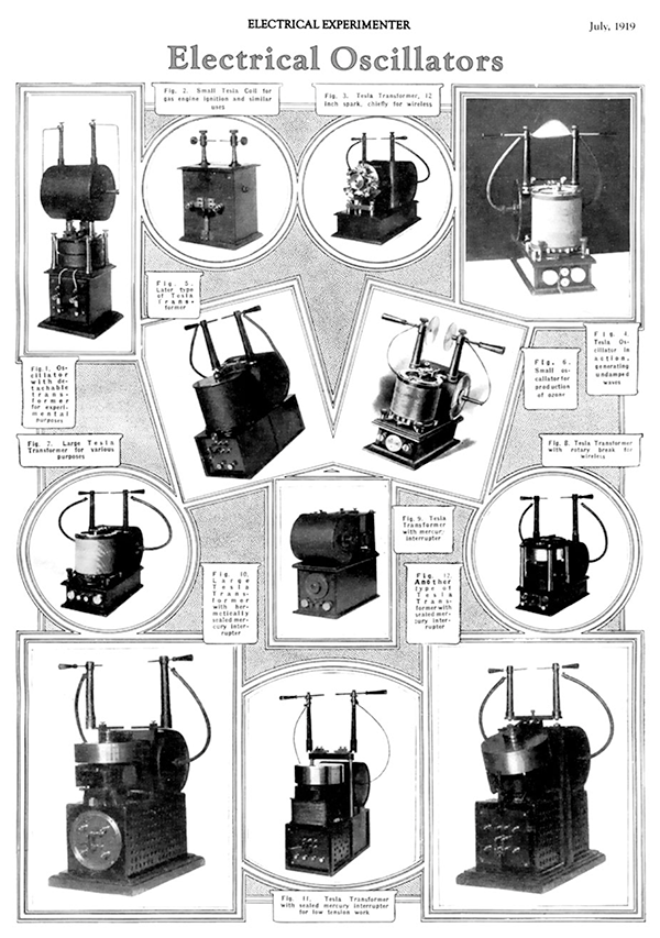
Electrical Oscillators
Few fields have been opened up the exploration of which has proved as fruitful as that of high frequency currents. Their singular properties and the spectacular character of the phenomena they presented immediately commanded universal attention. Scientific men became interested in their investigation, engineers were attracted by their commercial possibilities, and physicians recognized in them a long-sought means for effective treatment of bodily ills. Since the publication of my first researches in 1891, hundreds of volumes have been written on the subject and many invaluable results obtained through the medium of this new agency. Yet, the art is only in its infancy and the future has incomparably bigger things in store.
From the very beginning I felt the necessity of producing efficient apparatus to meet a rapidly growing demand and during the eight years succeeding my original announcements I developed not less than fifty types of these transformers or electrical oscillators, each complete in every detail and refined to such a degree that I could not materially improve any one of them today. Had I been guided by practical considerations I might have built up an immense and profitable business, incidentally rendering important services to the world. But the force of circumstances and the ever enlarging vista of greater achievements turned my efforts in other directions. And so it comes that instruments will shortly be placed on the market which, oddly enough, were perfected twenty years ago!
These oscillators are expressly intended to operate on direct and alternating lighting circuits and to generate damped and undamped oscillations or currents of any frequency, volume and tension within the widest limits. They are compact, self-contained, require no care for long periods of time and will be found very convenient and useful for various purposes as, wireless telegraphy and telephony; conversion of electrical energy; formation of chemical compounds through fusion and combination; synthesis of gases; manufacture of ozone; lighting; welding; municipal, hospital, and domestic sanitation and sterilization, and numerous other applications in scientific laboratories and industrial institutions. While these transformers have never been described before, the general principles underlying them were fully set forth in my published articles and patents, more particularly those of September 22, 1896, and it is thought, therefore, that the appended photographs of a few types, together with a short explanation, will convey all the information that may be desired.
The essential parts of such an oscillator are: a condenser, a self-induction coil for charging the same to a high potential, a circuit controller, and a transformer which is energized by the oscillatory. discharges of the condenser. There are at least three, but usually four, five or six, circuits in tune and the regulation is effected in several ways, most frequently merely by means of an adjusting screw. Under favorable conditions an efficiency as high as 85% is attainable, that is to say, that percentage of the energy supplied can be recovered in the secondary of the transformer. While the chief virtue of this kind of apparatus is obviously due to the wonderful powers of the condenser, special qualities result from concatenation of circuits under observance of accurate harmonic relations, and minimization of frictional and other losses which has been one of the principal objects of the design.
Broadly, the instruments can be divided into two classes: one in which the circuit controller comprises solid contacts, and the other in which the make and break is effected by mercury. Figures 1 to 8, inclusive, belong to the first, and the remaining ones to the second class. The former are capable of an appreciably higher efficiency on account of the fact that the losses involved in the make and break are reduced to the minimum and the resistance component of the damping factor is very small. The latter are preferable for purposes requiring larger output and a great number of breaks per second. The operation of the motor and circuit controller of course consumes a certain amount of energy which, however, is the less significant the larger the capacity of the machine.
In Fig. 1 is shown one of the earliest forms of oscillator constructed for experimental purposes. The condenser is contained in a square box of mahogany upon which is mounted the self-induction or charging coil wound, as will be noted, in two sections connected in multiple or series according to whether the tension of the supply circuit is 110 or 220 volts. From the box protrude four brass columns carrying a plate with the spring contacts and adjusting screws as well as two massive terminals for the reception of the primary of the transformer. Two of the columns serve as condenser connections while the other pair is employed to join the binding posts of the switch in front to the self-inductance and condenser. The primary coil consists of a few turns of topper ribbon to the ends of which are soldered short rods fitting into the terminals referred to. The secondary is made in two parts, wound in a manner to reduce as much as possible the distributed capacity and at the same time enable the coil to withstand a very high pressure between its terminals at the center, which are connected to binding posts on two rubber columns projecting from the primary. The circuit connections may be slightly varied but ordinarily they are as diagrammatically illustrated in the Electrical Experimenter for May on page 89, relating to my oscillation transformer photograph of which appeared on page 16 of the same number. The operation is as follows: When the switch is thrown on, the current from the supply circuit rushes through the self-induction coil, magnetizing the iron core within and separating the contacts of the controller. The high tension induced current then charges the condenser and upon closure of the contacts the accumulated energy is released through the primary, giving rise to a long series of oscillations which excite the tuned secondary circuit.
This device has proved highly serviceable in carrying on laboratory experiments of all kinds. For instance, in studying phenomena of impedance, the transformer was removed and a bent copper bar inserted in the terminals. The latter was often replaced by a large circular loop to exhibit inductive effects at a distance or to excite resonant circuits used in various investigations and measurements. A transformer suitable for any desired performance could be readily improvised and attached to the terminals and in this way much time and labor was saved. Contrary to what might be naturally expected, little trouble was experienced with the contacts, although the currents through them were heavy, namely, proper conditions of resonance existing, the great flow occurs only when the circuit is closed and no destructive arcs can develop. Originally I employed platinum and iridium tips but later replaced them by some of meteorite and finally of tungsten. The last have given the best satisfaction, permitting working for hours and days without interruption.
Fig. 2 illustrates a small oscillator designed for certain specific uses. The underlying idea was to attain great activities during minute intervals of time each succeeded by a comparatively long period of inaction. With this object a large self-induction and a quick-acting break were employed owing to which arrangement the condenser was charged to a very high potential. Sudden secondary currents and sparks of great volume were thus obtained, eminently suitable for welding thin wires, flashing lamp filaments, igniting explosive mixtures and kindred applications. The instrument was also adapted for battery use and in this form was a very effective igniter for gas engines on which a patent bearing number 609,250 (Electrical Ignitor for Gas Engines) was granted to me August 16,1898.

Fig. 3 represents a large oscillator of the first class intended for wireless experiments, production of Rontgen rays and scientific research in general. It comprises a box containing two condensers of the same capacity on which are supported the charging coil and transformer. The automatic circuit controller, hand switch and connecting posts are mounted on the front plate of the inductance spool as is also one of the contact springs. The condenser box is equipped with three terminals, the two external ones serving merely for connection while the middle one carries a contact bar with a screw for regulating the interval during which the circuit is closed. The vibrating spring, itself, the sole function of which is to cause periodic interruptions, can be adjusted in its strength as well as distance from the iron core in the center of the charging coil by four screws visible on the top plate so that any desired conditions of mechanical control might be secured. The primary coil of the transformer is of copper sheet and taps are made at suitable points for the purpose of varying at will., the number of turns. As in Fig. 1 the inductance coil is wound in two sections to adapt the instrument both to 110 and 220 volt circuits and several secondaries were provided to suit the various wave lengths of the primary. The output was approximately 500 watt with damped waves of about 50,000 cycles per second. For short periods of time undamped oscillations were produced in screwing the vibrating spring tight against the iron core and separating the contacts by the adjusting screw which also performed the function of a key. With this oscillator I made a number of important observations and it was one of the machines exhibited at a lecture before the New York Academy of Sciences in 1897.
Fig. 4 is a photograph of a type of transformer in every respect similar to the one illustrated in the May, 1919, issue of the Electrical Experimenter to which reference has already been made. It contains the identical essential parts, disposed in like manner, but was specially designed for use on supply circuits of higher tension, from 220 to 500 volts or more. The usual adjustments are made in setting the contact spring and shifting the iron core within the inductance coil up and down by means of two screws. In order to prevent injury through a short-circuit, fuses are inserted in the lines. The instrument was photographed in action, generating undamped oscillations from a 220 volt lighting circuit.
Fig. 5 shows a later form of transformer principally intended to replace Rhumkorf coils. In this instance a primary is employed, having a much greater number of turns and the secondary is closely linked with the same. The currents developed in the latter, having a tension of from 10,000 to 30,000 volts, are used to charge condensers and operate an independent high frequency coil as customary. The controlling mechanism is of somewhat different construction but the core and contact spring are both adjustable as before.
Fig. 6 is a small instrument of this type, particularly intended for ozone production or sterilization. It is remarkably efficient for its size and can be connected either to a 110 or 220 volt circuit, direct or alternating, preferably the former.
In Fig. 7 is shown a photograph of a larger transformer of this kind. The construction and disposition of the parts is as before but there are two condensers in the box, one of which is connected in the circuit as in the previous cases, while the other is in shunt to the primary coil. In this manner currents of great volume are produced in the latter and the secondary effects are accordingly magnified. The introduction of an additional tuned circuit secures also other advantages but the adjustments are rendered more difficult and for this reason it is desirable to use such an instrument in the production of currents of a definite and unchanging frequency.
Fig. 8 illustrates a transformer with rotary break. There are two condensers of the same capacity in the box which can be connected in series or multiple. The charging inductances are in the form of two long spools upon which are supported the secondary terminals. A small direct current motor, the speed of which can be varied within wide limits, is employed to drive a specially constructed make and break. In other features the oscillator is like the one illustrated in Fig. 3 and its operation will be readily understood from the foregoing. This transformer was used in my wireless experiments and frequently also for lighting the laboratory by my vacuum tubes and was likewise exhibited at my lecture before the New York Academy of Sciences above mentioned.
Coming now to machines of the second class, Fig. 9 shows an oscillatory transformer comprising a condenser and charging inductance enclosed in a box, a transformer and a mercury circuit controller, the latter being of a construction described for the first time in my patent No. 609,251 (Electric Circuit Controller) of August 16, 1898. It consists of a motor driven hollow pulley containing a small quantity of mercury which is thrown outwardly against the walls of the vessel by centrifugal force and entrains a contact wheel which periodically closes and opens the condenser circuit. By means of adjusting screws above the pulley, the depth of immersion of the vanes and consequently, also, the duration of each contact can be varied at desire and thus the intensity of the effects and their character controlled. This form of break has given thorough satisfaction, working continuously with currents of from 20 to 25 amperes. The number of interruptions is usually from 500 to 1,000 per second but higher frequencies are practicable. The space occupied is about 10" X 8" X 10" and the output approximately 1/2 kW.
In the transformer just described the break is exposed to the atmosphere and a slow oxidation of the mercury takes place. This disadvantage is overcome in the instrument shown in Fig. 10, which consists of a perforated metal box containing the condenser and charging inductance and carrying on the top a motor driving the break, and a transformer. The mercury break is of a kind to be described and operates on the principle of a jet which establishes, intermittently, contact with a rotating wheel in the interior of the pulley. The stationary parts are supported in the vessel on a bar passing through the long hollow shaft of the motor and a mercury seal is employed to effect hermetic closure of the chamber enclosing the circuit controller. The current is led into the interior of the pulley through two sliding rings on the top which are in series with the condenser and primary. The exclusion of the oxygen is a decided improvement, the deterioration of the metal and attendant trouble being eliminated and perfect working.
Fig. 11 is a photograph of a similar oscillator with hermetically inclosed mercury break. In this machine the stationary parts of the interrupter in the interior of the pulley were supported on a tube through which was led an insulated wire connecting to one terminal of the break while the other was in contact with the vessel. The sliding rings were, in this manner, avoided and the construction simplified. The instrument was designed for oscillations of lower tension and frequency requiring primary currents of comparatively smaller amperage and was used to excite other resonant circuits.
Fig. 12 shows an improved form of oscillator of the kind described in Fig. 10, in which the supporting bar through the hollow motor shaft was done away with, the device pumping the mercury being kept in position by gravity, as will be more fully explained with reference to another figure. Both the capacity of the condenser and primary turns were made variable with the view of producing oscillations of several frequencies.

Fig. 13 is a photographic view of another form of oscillatory transformer with hermetically sealed mercury interrupter, and Fig. 14 diagrams showing the circuit connections and arrangement of parts reproduced from my patent, No. 609,245 (Electrical Circuit Controller), of August 16, 1898, describing this particular device. The condenser, inductance, transformer and circuit controller are disposed as before, but the latter is of different construction, which will be clear from an inspection of Fig. 14: The hollow pulley a is secured to a shaft c which is mounted in a vertical bearing passing through the stationary field magnet d of the motor. In the interior of the vessel is supported, on frictionless bearings, a body h of magnetic material which is surrounded by a dome b in the center of a laminated iron ring, with pole pieces oo wound with energizing coils p. The ring is supported on four columns and, when magnetized, keeps the body h in position while the pulley is rotated. The latter is of steel, but the dome is preferably made of German silver burnt black by acid or nickeled. The body h carries a short tube k bent, as indicated, to catch the fluid as it is whirled around, and project it against the teeth of a wheel fastened to the pulley. The wheel is insulated and contact from it to the external circuit is established through a mercury cup. As the pulley is rapidly rotated a jet of the fluid is thrown against the wheel, thus peaking and breaking contact about 1,000 times per second. The instrument works silently and, owing to the absence of all deteriorating agents; keeps continually clean and in perfect condition. The number of interruptions per second may be much greater, however, so as to make the currents suitable for wireless telephony and like purposes.
A modified form of oscillator is represented in Figs. 15 and 16, the former being a photographic view and the latter a diagrammatic illustration showing the arrangement of the interior parts of the controller. In this instance the shaft b carrying the vessel a is hollow and supports, in frictionless bearings, a spindle j to which is fastened a weight k. Insulated from the latter, but mechanically fixed to it, is a curved arm L upon which is supported, freely rotatable, a break-wheel with projections QQ. The wheel is in electrical connection with the external circuit through a mercury cup and an insulated plug supported from the top of the pulley. Owing to the inclined position of the. motor the weight k keeps the break-wheel in place by the force of gravity and as the pulley is rotated the circuit, including the condenser and primary coil of the transformer, is, rapidly made and broken.

Fig. 17 shows a similar instrument in which, however, the make and break device is a jet of mercury impinging against an insulated toothed wheel carried on an insulated stud in the center of the cover of the pulley as shown. Connection to the condenser circuit is made by brushes bearing on this plug.
Fig. 18 is a photograph of another transformer with a mercury circuit controller of the wheel type, modified in some features on which it is unnecessary to dwell.
These are but a few of the oscillatory transformers I have perfected and constitute only a small part of my high frequency apparatus of which I hope to give a full description, when I shall have freed myself of pressing duties, at some future date.
Write a comment
Pengobatan Alternatif Pengapuran Sendi (Wednesday, 30 August 2017 05:39)
article very helpful, thanks
Cara Cepat Membersihkan Rahim Pasca Melahirkan (Tuesday, 12 September 2017 09:47)
thanks for sharing this article
Obat Herbal Patah Tulang Kelingking Alami (Thursday, 14 September 2017 09:48)
article very helpful, thanks
Obat Alami Pembersih Kandungan Setelah Keguguran (Tuesday, 19 September 2017 04:10)
This is an excellent blog post! Thank you for sharing with us!
obat yang dapat membuat pria perkasa saat berhubungan intim (Saturday, 30 September 2017 06:02)
this article is very good and jangn to miss to read it
Obat Tulang Keropos (Saturday, 07 October 2017 05:32)
article very helpful, thanks
Cara Mengatasi Buah Zakar Besar Sebelah (Monday, 09 October 2017 08:27)
Thank you , very useful article
Jamu Pembersih Kandungan Pasca Keguguran (Saturday, 21 October 2017 08:24)
articles were awesome and very helpful, thank you very much
Cara Cepat Membersihkan Darah Di Rahim (Thursday, 26 October 2017 08:56)
thank you for sharing the information that interests us all, may be beneficial