 Inventions & Experiments
of Nikola Tesla
Inventions & Experiments
of Nikola Tesla
The Tesla Steam Turbine
http://www.teslauniverse.com/nikola-tesla-article-the-tesla-steam-turbine
http://www.teslauniverse.com/pdf/articles/19110930-01.pdf
Scientific American
September 30th, 1911

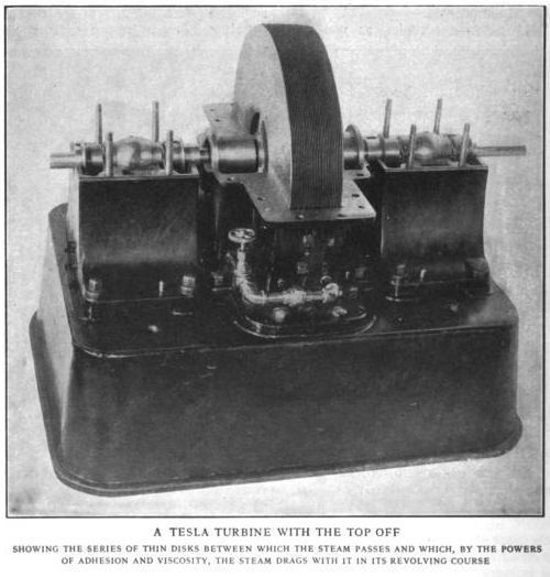
The top half of casings is removed, showing two rotors. Each rotor consists of 25 disks 3/8-inch thick by 18 inch diameter. The steam enters at the periphery, and flows in spiral paths to exhaust at the center of the disks. The driving turbine is to the left, the brake turbine to the right. Between them is a torsion spring. The steam inlets are on opposite sides on the two rotors; the driving rotor moving clockwise. The torsion of the spring is automatically shown by beams of light and mirrors and the horse-power is read off a scale. At 9,000 revolutions per minute, with 125 pounds at the throttle and free exhaust, this turbine develops 200 horse-power. It weighs two pounds per horse-power.
The Rotary Heat Motor Reduced to Its Simplest Terms
It will interest the readers of the Scientific American to know that Nikola Tesla, whose reputation must, naturally, stand upon the contributions he made to electrical engineering when the art was yet in its comparative infancy, is by training and choice a mechanical engineer, with a strong leaning to that branch of it which is covered by the term “steam engineering.” For several years past he has devoted much of his attention to improvements in thermo-dynamic conversion, and the result of his theories and practical experiments is to be found in an entirely new form of prime movers shown in operation at the Waterside station of the New York Edison Company, who kindly placed the facilities of their great plant at his disposal for carrying on experimental work.
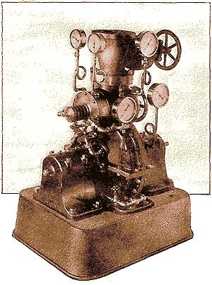
By the courtesy of the inventor, we are enabled to publish the accompanying views, representing the testing plant at the Waterside station, which are the first photographs of this interesting motor that have yet been made public.
The basic principle which determined Tesla’s investigations was the well-known fact that when a fluid (steam, gas or water) is used as a vehicle of energy, the highest possible economy can be obtained only when the changes in velocity and direction of the movement of the fluid are made as gradual and easy as possible. In the present forms of turbines in which the energy is transmitted by pressure, reaction or impact, as in the De Laval, Parsons, and Curtiss types, more or less sudden changes both of speed and direction are involved, with consequent shocks, vibration and destructive eddies. Furthermore, the introduction of pistons, blades, buckets, and intercepting devices of this general class, into the path of the fluid involves much delicate and difficult mechanical construction which adds greatly to the cost both of production and maintenance.
The desiderata in an ideal turbine group themselves under the heads of the theoretical and the mechanical. The theoretically perfect turbine would be one in which the fluid was so controlled from the inlet to the exhaust that its energy was delivered to the driving shaft with the least possible losses due to the mechanical means employed. The mechanically, perfect turbine would be one which combined simplicity and cheapness of construction, durability, ease and rapidity of repairs, and a small ratio of weight and space occupied to the power delivered on the shaft. Mr. Tesla maintains that in the turbine which forms the subject of this article, he has carried the steam and gas motor a long step forward toward the maximum attainable efficiency, both theoretical and mechanical. That these claims are well founded is shown by the fact that in the plant at the Edison station, he is securing an output of 200 horse-power from a single-stage steam turbine with atmospheric exhaust, weighing less than 2 pounds per horse-power, which is contained within a space measuring 2 feet by 3 feet, by 2 feet in height, and which accomplishes these results with a thermal fall of only 130 B.T.U., that is, about one-third of the total drop available. Furthermore, considered from the mechanical standpoint, the turbine is astonishingly simple and economical in construction, and by the very nature of its construction, should prove to possess such a durability and freedom from wear and breakdown as to place it, in these respects, far in advance of any type of steam or gas motor of the present day.
Briefly stated, Tesla’s steam motor consists of a set of flat steel disks mounted on a shaft and rotating within a casing, the steam entering with high velocity at the periphery of the disks, flowing between them in free spiral paths, and finally escaping through exhaust ports at their center. Instead of developing the energy of the steam by pressure, reaction, or impact, on a series of blades or vanes, Tesla depends upon the fluid properties of adhesion and viscosity — the attraction of the steam to the faces of the disks and the resistance of its particles to molecular separation combining in transmitting the velocity energy of the motive fluid to the plates and the shaft.
By reference to the accompanying photographs and line drawings, it will be seen that the turbine has a rotor A which in the present case consists of 25 flat steel disks, one thirty-second of an inch in thickness, of hardened and carefully tempered steel. The rotor as assembled is 3½ inches wide on the face, by 18 inches in diameter, and when the turbine is running at its maximum working velocity, the material is never under a tensile stress exceeding 50,000 pounds per square inch. The rotor is mounted in a casing D, which is provided with two inlet nozzles, B for use in running direct and B’ for reversing. Openings C are cut out at the central portion of the disks and these communicate directly with exhaust ports formed in the side of the casing.
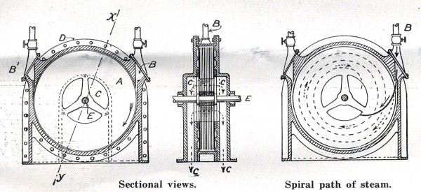
In operation, the steam, or gas, as the case may be, is directed on the periphery of the disks through the nozzle B (which may be diverging, straight or converging), where more or less of its expansive energy is converted into velocity energy. When the machine is at rest, the radial and tangential forces due to the pressure and velocity of the steam cause it to travel in a rather short curved path toward the central exhaust opening, as indicated by the full black line in the accompanying diagram; but as the disks commence to rotate and their speed increases, the steam travels in spiral paths the length of which increases until as in the case of the present turbine, the particles of the fluid complete a number of turns around the shaft before reaching the exhaust, covering in the meantime a lineal path some 12 to 16 feet in length. During its progress from inlet to exhaust, the velocity and pressure of the steam are reduced until it leaves the exhaust at 1 or 2 pounds gauge pressure.
The resistance to the passage of the steam or gas between adjoining plates is approximately proportionate to the square of the relative speed, which is at a maximum toward the center of the disks and is equal to the tangential velocity of the steam. Hence the resistance to radial escape is very great, being furthermore enhanced by the centrifugal force acting outwardly. One of the most desirable elements in a perfected turbine is that of reversibility, and we are all familiar with the many and frequently cumbersome means which have been employed to secure this end. It will be seen that this turbine is admirably adapted for reversing, since this effect can be secured by merely closing the right-hand valve and opening that on the left.
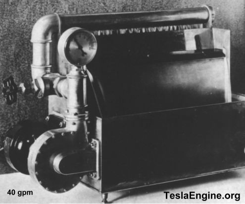
It is evident that the principles of this turbine are equally applicable, by slight modifications of design, for its use as a pump, and we present a photograph of a demonstration model which is in operation in Mr. Tesla’s office. This little pump, driven by an electric motor of 1/12 horse-power, delivers 40 gallons per minute against a head of 9 feet. The discharge pipe leads up to a horizontal tube provided with a wire mesh for screening the water and checking the eddies. The water falls through a slot in the bottom of this tube and after passing below a baffle plate flows in a steady stream about ¾ inch thick by 18 inches in width, to a trough from which it returns to the pump. Pumps of this character show an efficiency favorably comparing with that of centrifugal pumps and they have the advantage that great heads are obtainable economically in a single stage. The runner is mounted in a two-part volute casing and except for the fact that the place of the buckets, vanes, etc., of the ordinary centrifugal pump is taken by a set of disks, the construction is generally similar to that of pumps of the standard kind.
In conclusion, it should be noted that although the experimental plant at the Waterside station develops 200 horse-power with 125 pounds at the supply pipe and free exhaust, it could show an output of 300 horse-power with the full pressure of the Edison supply circuit. Furthermore, Mr. Tesla states that if it were compounded and the exhaust were led to a low pressure unit, carrying about three times the number of disks contained in the high pressure element, with connection to a condenser affording 28½ to 29 inches of vacuum, the results obtained in the present high-pressure machine indicate that the compound unit would give an output of 600 horse-power, without great increase of dimensions. This estimate is conservative.
The testing plant consists of of two identical turbines connected by a carefully calibrated torsion spring, the machine to the left being the driving element, the other the brake. In the brake element, the steam is delivered to the blades in a direction opposite to that of the rotation of the disks. Fastened to the shaft of the brake turbine is a hollow pulley provided with two diametrically opposite narrow slots, and an incandescent lamp placed inside close to the rim. As the pulley rotates, two flashes of light pass out of the same; and by means of reflecting mirrors and lenses, they are carried around the plant and fall upon two rotating glass mirrors placed back to back on the shaft of the driving turbine so that the center line of the silver coatings coincides with the axis of the shaft. The mirrors are so set that when there is no torsion on the spring, the light beams produce a luminous spot stationary at the zero of the scale. But as soon as load is put on, the beam is deflected through an angle which indicates directly the torsion. The scale and spring are so proportioned and adjusted that the horse-power can be read directly from the deflections noted. The indications of this device are very accurate and have shown that when the turbine is running at 9,000 revolutions under an inlet pressure of 125 pounds to the square inch, and with free exhaust, 200 brake horse-power are developed. The consumption under these conditions of maximum output is 38 pounds of saturated steam per horse-power per hour — a very high efficiency when we consider that the heat-drop, measured by thermometers, is only 130 B.T.U., and that the energy transformation is effected in one stage. Since about three times this number of heat units are available in a modern plant with superheat and high vacuum, the above means a consumption of less than 12 pounds per horse-power hour in such turbines adapted to take up the full drop. Under certain conditions, however, very high thermal efficiencies have been obtained which demonstrate that in large machines based on this principle, in which a very small slip can be secured, the steam consumption will be much lower and should, Mr. Tesla states, approximate the theoretical minimum, thus resulting in nearly frictionless turbine transmitting almost the entire expansive energy of the steam to the shaft.
Write a comment