 Inventions & Experiments
of Nikola Tesla
Inventions & Experiments
of Nikola Tesla
On the Source of Roentgen Rays and the Practical Construction and Safe Operation of Lenard Tubes
by Nikola Tesla
I have for some time felt that a few indications in regard to the practical construction of Lenard tubes of improved designs, a great number of which I have recently exhibited before the New York Academy of Sciences (April 6, 1897), would be useful and timely, particularly as by their proper construction and use much of the danger attending the experimentation with the rays may be avoided. The simple precautions which I have suggested in my previous communications are seemingly disregarded, and cases of injury to patients are being almost daily reported, and in view of this only, were it for no other reason, the following lines, referring to this subject, would have been written before had not again pressing and unavoidable duties prevented me from doing so. A short and, I may say, most unwelcome interruption of the work which has been claiming my attention makes this now possible. However, as these opportunities are scarce, I will utilize the present to dwell in a few words on some other matters in connection with this subject, and particularly on a result of importance which I have reached some time ago by the aid of such a Lenard tube, and which, if I am correctly informed, I can only in part consider as my own, since it seems that practically it has been expressed in other words by Professor Roentgen in a recent communication to the Academy of Sciences of Berlin. The result alluded to has reference to the much disputed question of the source of the Roentgen rays. As will be remembered, in the first announcement of his discovery, Roentgen was of the opinion that the rays which affected the sensitive layer emanated from the fluorescent spot on the glass wall of the bulb; other scientific men next made the cathode responsible; still others the anode, while some thought that the rays were emitted solely from fluorescent powders of surfaces, and speculations, mostly unfounded, increased to such an extent that, despairingly, one would exclaim with the poet:
“O glücklich wer noch hoffen kann,
Aus diesem Meer des Irrtums aufzutauchen!”
My own experiments led me to recognize that, regardless of the location, the chief source of these rays was the place of the first impact of the projected stream of particles within the bulb. This was merely a broad statement, of which that of Professor Roentgen was a special case, as in his first experiments the fluorescent spot on the glass wall was, incidentally, the place of the first impact of the cathodic stream. Investigations carried on up to the present day have only confirmed the correctness of the above opinion, and the place of the first collision of the stream of particles — be it an anode or independent impact body, the glass wall or an aluminum window — is still found to be the principal source of the rays. But, as will be seen presently, it is not the only source.
Since recording the above fact my efforts were directed to finding answers to the following questions: First, is it necessary that the impact body should be within the tube? Second, is it required that the obstacle in the path of the cathodic stream should be a solid or liquid? And, third, to what extent is the velocity of the stream necessary for the generation of and influence upon the character of the rays emitted?

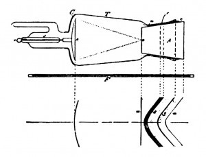
In order to ascertain whether a body located outside of the tube and in the path or in the direction of the stream of particles was capable of producing the same peculiar phenomena as an object located inside, it appeared necessary to first show that there is an actual penetration of the particles through the wall, or otherwise that the actions of the supposed streams, of whatever nature they might be, were sufficiently pronounced in the outer region close to the wall of the bulb as to produce some of the effects which are peculiar to a cathodic stream. It was not difficult to obtain with a properly prepared Lenard tube, having an exceedingly thin window, many and at first surprising evidences of this character. Some of these have already been pointed out, and it is thought sufficient to cite here one more which I have since observed. In the hollow aluminum cap A of a tube as shown in diagram Fig. 1, which will be described in detail, I placed a half-dollar silver piece, supporting it at a small distance from and parallel to the window or bottom of the cap by strips of mica in such a manner that it was not touching the metal of the tube, an air space being left all around it. Upon exciting the bulb for about 30 to 45 seconds by the secondary discharge of a powerful coil of a novel type now well known, it was found that the silver piece was rendered so hot as to actually scorch the hand; yet the aluminum window, which offered a very insignificant obstacle to the cathodic stream, was only moderately warmed. Thus it was shown that the silver alloy, owing to its density and thickness, took up most of the energy of the impact, being acted upon by the particles almost identically as if it had been inside of the bulb, and, what is more, indications were obtained, by observing the shadows, that it behaved like a second source of the rays, inasmuch as the outlines of the shadows, instead of being sharp and clear as when the half-dollar piece was removed, were dimmed. It was immaterial for the chief object of the inquiry to decide by more exact methods whether the cathodic particles actually penetrated the window, or whether a new and separate stream was projected from the outer side of the window. In my mind there exists not the least doubt that the former was the case, as in this respect I have been able to obtain numerous additional proofs, upon which I may dwell in the near future.
Now, in looking upon the screen in the direction from F to T, the dark lines indicated on the lower part of the diagram were seen on the illuminated background. The curved line e and the straight line W were, of course, at once recognized as the outlines of the cathode e and the bottom of the cap A respectively, although, in consequence of a confusing optical illusion, they appeared mush closer together than they actually were. For instance, if the distance between e and o was five inches, these lines would appear on the screen about two inches apart, as nearly as I could judge by the eye. This illusion may be easily explained and is quite unimportant, except that it might be of some moment to physicians to keep this fact in mind when making examinations with the screen as, owing to the above effect, which is sometimes exaggerated to a degree hard to believe, a completely erroneous idea of the distance of the various parts of the object under examination might be gained, to the detriment of the surgical operation. But while the lines e and W were easily accounted for, the curved lines t, g, a were at first puzzling. Soon, however, it was ascertained that the faint line a was the shadow of the edge of the aluminum cap, the much darker line g that of the rim of the glass tube T, and t the shadow of the tinfoil ring r. These shadows on the screen F clearly showed that the agency which affected the fluorescent material was proceeding from the space outside of the bulb towards the aluminum cap, and chiefly from the region through which the primary disturbances or streams emitted from the tube through the window were passing, which observation could not be explained in a more plausible manner than by assuming that the air and dust particles outside, in the path of the projected streams, afforded an obstacle to their passage and gave rise to impacts and collisions spreading through the air in all directions, thus producing continuously new sources of the rays. It is this fact which, in his recent communication before mentioned, Roentgen has brought out. So, at least, I have interpreted his reported statement that the rays emanate from the irradiated air. It now remains to be shown whether the air, from which carefully all foreign particles are removed, is capable of behaving as an impact body and source of the rays, in order to decide whether the generation of the latter is dependent on the presence in the air of impact particles of measurable dimensions. I have reasons to think so.
With the knowledge of this fact we are now able to form a more general idea of the process of generation of the radiations which have been discovered by Lenard and Roentgen. It may be comprised in the statement that the streams of minute material particles projected from an electrode with great velocity in encountering obstacles wherever they may be, within the bulb, in the air or other medium or in the sensitive layers themselves, give rise to rays or radiations possessing many of the properties of those known as light. If this physical process of generation of these rays is undoubtedly demonstrated as true, it will have most important consequences, as it will induce physicists to again critically examine many phenomena which are presently attributed to transverse ether waves, which may lead to a radical modification of existing views and theories in regard to these phenomena, if not as to their essence so, at least, as to the mode of their production.
My effort to arrive at an answer to the third of the above questions led me to the establishment, by actual photographs, of the close relationship which exists between the Lenard and Roentgen rays. The photographs bearing on this point were exhibited at a meeting of the New York Academy of Sciences — before referred to — April 6, 1897, but, unfortunately, owing to the shortness of my address, and concentration of thought on other matters, I omitted what was most important; namely, to describe the manner in which these photographs were obtained, an oversight which I was able to only partially repair the day following. I did, however, on that occasion illustrate and describe experiments in which was shown the deflectibility of the Roentgen rays by a magnet, which establishes a still closer relationship, if not identity, of the rays named after these two discoverers. But the description of these experiments in detail, as well as of other investigations and results in harmony with and restricted to the subject I brought before that scientific body, will appear in a longer communication which I am slowly preparing.
To bring out clearly the significance of the photographs in question, I would recall that, in some of my previous contributions to scientific societies, I have endeavored to dispel a popular opinion before existing that the phenomena known as those of Crookes were dependent on and indicative of high vacua. With this object in view, I showed that phosphorescence and most of the phenomena in Crookes bulbs were producible at greater pressures of the gases in the bulbs by the use of much higher or more sudden electro-motive impulses. Having this well demonstrated fact before me, I prepared a tube in the manner described by Lenard in his first classical communication on this subject. The tube was exhausted to a moderate degree, either by chance or of necessity, and it was found that, when operated by an ordinary high-tension coil of a low rate of change in the current, no rays of any of the two kinds could be detected, even when the tube was so highly strained as to become very hot in a few moments. Now, I expected that, if the suddenness of the impulses through the bulb were sufficiently increased, rays would be emitted. To test this I employed a coil of a type which I have repeatedly described, in which the primary is operated by the discharges of a condenser. With such an instrument any desired suddenness of the impulses may be secured, there being practically no limit in this respect, as the energy accumulated in the condenser is the most violently explosive agent we know, and any potential or electrical pressure is obtainable. Indeed, I found that in increasing the suddenness of the electro-motive impulses through the tube — without, however, increasing, but rather diminishing the total energy conveyed to it — phosphorescence was observed and rays began to appear, first the feebler Lenard rays and later, by pushing the suddenness far enough, Roentgen rays of great intensity, which enabled me to obtain photographs showing the finest texture of the bones. Still, the same tube, when again operated with the ordinary coil of a low rate of change in the primary current, emitted practically no rays, even when, as before stated, much more energy, as judged from the heating, was passed through it. This experience, together with the fact that I have succeeded in producing by the use of immense electrical pressures, obtainable with certain apparatus designed for this express purpose, some impressions in free air, have led me to the conclusion that in lightning discharges Lenard and Roentgen rays must be generated at ordinary atmospheric pressure.
At this juncture I realize, by a perusal of the preceding lines, that my scientific interest has dominated the practical, and that the following remarks must be devoted to the primary object of this communication — that is, to giving some data for the construction to those engaged in the manufacture of the tubes and, perhaps, a few useful hints to practicing physicians who are dependent on such information. The foregoing was, nevertheless, not lost for this object, inasmuch as it has shown how much the result obtained depends on the proper construction of the instruments, for, with ordinary implements, most of the above observations could not have been made.
I have already described the form of tube illustrated in Fig. 1, and in Fig. 2 another still further improved design is shown. In this case the aluminum cap A, instead of having a straight bottom as before, is shaped spherically, the center of the sphere coinciding with that of the electrode e, which itself, as in Fig. 1, has its focus in the center of the window of cap A, as indicated by the dotted lines. The aluminum cap A has a tinfoil ring r, as that in Fig. 1, or else the metal of the cap is spun out on that place so as to afford a bearing of small surface between the metal and the glass. This is an important practical detail as, by making the bearing surface small, the pressure per unit of area is increased and a more perfect joint made. The ring r should be first spun out and then ground to fit the neck of the bulb. If a tinfoil ring is used instead, it may be cut out of one of the ordinary tinfoil caps obtainable in the market, care being taken that the ring is very smooth.
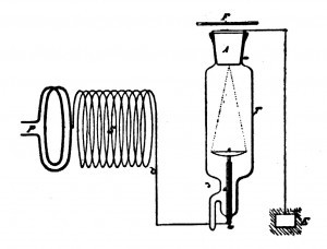
In Fig. 3 I have shown a modified design of tube which, as the two types before described, was comprised in the collection I exhibited. This, as will be observed, is a double-focus tube, with impact plates of iridium alloy and an aluminum cap A opposite the same. The tube is not shown because of any originality in design, but simply to illustrate a practical feature. It will be noted that the aluminum caps in the tubes described are fitted inside of the necks and not outside, as is frequently done. Long experience has demonstrated that it is practically impossible to maintain a high vacuum in a tube with an outside cap. The only way I have been able to do this in a fair measure is by cooling the cap by a jet of air, for instance, and observing the following precautions: The air jet is first turned on slightly and upon this the tube is excited. The current through the latter, and also the air pressure, are then gradually increased and brought to the normal working condition. Upon completing the experiment the air pressure and current through the tube are both gradually reduced and both so manipulated that no great differences in temperature result between the glass and aluminum cap. If those precautions are not observed the vacuum will be immediately impaired in consequence of the uneven expansion of the glass and metal.
With tubes, as these presently described, it is quite unnecessary to observe this precaution if proper care is taken in their preparation. In inserting the cap the latter is cooled down as low as it is deemed advisable without endangering the glass, and it is then gently pushed in the neck of the tube, taking care that it sets straight.
The two most important operations in the manufacture of such a tube are, however, the thinning down of the aluminum window and the sealing in of the cap. The metal of the latter may be one thirty-second or even one-sixteenth of an inch thick, and in such case the central portion may be thinned down by a countersink tool about one-fourth of an inch in diameter as far as it is possible without tearing the sheet. The further thinning down may then be done by hand with a scraping tool; and, finally, the metal should be gently beaten down so as to surely close the pores which might permit a slow leak. Instead of proceeding in this way I have employed a cap with a hole in the center, which I have closed with a sheet of pure aluminum a few thousandths of an inch thick, riveted to the cap by means of a washer of thick metal, but the results were not quite as satisfactory.
In sealing the cap I have adopted the following procedure: The tube is fastened on the pump in the proper position and exhausted until a permanent condition is reached. The degree of exhaustion is a measure of perfection of the joint. The leak is usually considerable, but this is not so serious a defect as might be thought. Heat is now gradually applied to the tube by means of a gas stove until a temperature up to about the boiling point of sealing wax is reached. The space between the cap and the glass is then filled with sealing wax of good quality; and, when the latter begins to boil, the temperature is reduced to allow its settling in the cavity. The heat is then again, increased, and this process of heating and cooling is repeated several times until the entire cavity, upon reduction of the temperature, is found to be filled uniformly with the wax, all bubbles having disappeared. A little more wax is then put on the top and the exhaustion carried on for an hour or so, according to the capacity of the pump, by application of moderate heat much below the melting point of the wax.
A tube prepared in this manner will maintain the vacuum very well, and will last indefinitely. If not used for a few months, it may gradually lose the high vacuum, but it can be quickly worked up. However, if after long use it becomes necessary to clean the tube, this is easily done by gently warming it and taking off the cap. The cleaning may be done first with acid, then with highly diluted alkali, next with distilled water, and finally with pure rectified alcohol.
These tubes, when properly prepared, give impressions much sharper and reveal much more detail than those of ordinary make. It is important for the clearness of the impressions that the electrode should be properly shaped, and that the focus should be exactly in the center of the cap or slightly inside. In fitting in the cap, the distance from the electrode should be measured as exactly as possible. It should also be remarked that the thinner the window, the sharper are the impressions, but it is not advisable to make it too thin, as it is apt to melt in a point on turning on the current.
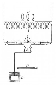
The above advantages are not the only ones which these tubes offer. They are also better adapted for purposes of examination by surgeons, particularly if used in the peculiar manner illustrated in diagrams Fig. 3 and Fig. 4, which are self-explanatory. It will be seen that in each of these the cap is connected to the ground. This decidedly diminishes the injurious action and enables also to take impressions with very short exposures of a few seconds only at close range, inasmuch as, during the operation of the bulb, one can easily touch the cap without any inconvenience, owing to the ground connection. The arrangement shown in Fig. 4 is particularly advantageous with a form of single terminal, which coil I have described on other occasions and which is diagrammatically illustrated, P being the primary and S the secondary. In this instance the high-potential terminal is connected to the electrode, while the cap is grounded. The tube may be placed in the position indicated in the drawing, under the operating table and quite close or even in contact with the body of the patient, if the impression requires only a few seconds as, for instance, in examining parts of the members. I have taken many impressions with such tubes and have observed no injurious action, but I would advise not to expose for longer than two or three minutes at very short distances. In this respect the experimenter should bear in mind what I have stated in previous communications. At all events it is certain that, in proceeding in the manner described, additional safety is obtained and the process of taking impressions much quickened. To cool the cap, a jet of air may be used, as before stated, or else a small quantity of water may be poured in the cap each time when an impression is taken. The water only slightly impairs the action of the tube, while it maintains the window at a safe temperature. I may add that the tubes are improved by providing back of the electrode a metallic coating C, shown in Fig. 3 and Fig. 4.
Write a comment
X-ray technician schools (Saturday, 05 October 2013 14:29)
Keep it up; keep posting more n more n more.
Boresi Fencing Suppliers in Sydney (Monday, 15 May 2017 15:33)
Having had opportunities to make many observations during my experience with vacuum bulbs and tubes